EM-18 RFID Reader Module is the one the most commonly used module for Radio Frequency Identification Projects. It features Low Cost, Small Size, Low Power Consumption and Easy to use. It can be directly interfaced with microcontrollers using UART communication. Software UART can be used for microcontrollers having no UART modules. In this tutorial we will see How to Interface EM-18 RFID Reader Module with PIC 16F877A Microcontroller. By understanding the basic idea, you will be able to interface it with any microcontrollers.
![Interfacing EM-18 RFID Module with PIC Microcontroller]() Working
Working
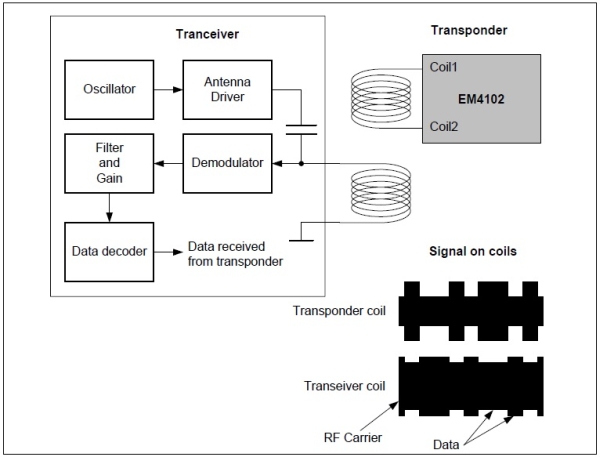
The EM-18 RFID Reader module generates and radiates RF Carrier Signals of frequency 125KHz through its coils. When a 125KHz Passive RFID Tag (have no battery) is brought in to this field, will get energized from it. These RFID Tags are usually made using a CMOS IC EM4102. It gets enough power and master clock for its operations from the electromagnetic fields produced by RFID Reader.
By changing the modulation current through the coils, tag will send back the information contained in the factory programmed memory array.
Interfacing with PIC Microcontroller
EM-18 RFID Reader Module can be directly interfaced with 5V PIC Microcontrollers using UART module. For 3.3V deviced you need to add additional voltage divider resistors to reduce 5V to 3.3V. You may also use Software UART if a dedicated UART module is not available.
 When a RFID Tag is bring in to the field of EM-18 RFID Reader, it will read its tag number and give output via TX terminal. The BEEP terminal will become LOW to indicate valid tag detection. The UART output will be 12 ASCII data, among these first 10 will be tag number and last 2 will be XOR result of the tag number which can be used for error testing.
For eg : If the RFID tag number is 500097892E, output of EM-18 Reader will be 500097892E60 where 60 is 50 xor 00 xor 97 xor 89 xor 2E.
For more detail: Interfacing EM-18 RFID Module with PIC Microcontroller
The post Interfacing EM-18 RFID Module with PIC Microcontroller appeared first on PIC Microcontroller.