Figure 1 shows the basic relay driver circuit. As you can see an NPN transistor BC547 is being used to control the relay. The transistor is driven into saturation (turned ON) when a LOGIC 1 is written on the PORT PIN thus turning ON the relay. The relay is turned OFF by writing LOGIC 0 on the port pin. A diode (1N4007/1N4148) is connected across the relay coil; this is done so as to protect the transistor from damage due to the BACK EMF generated in the relay’s inductive coil when the transistor is turned OFF. When the transistor is switched OFF the energy stored in the inductor is dissipated through the diode & the internal resistance of the relay coil. Normally 1N4148 can be used as it is fast switching diode with a maximum forward current of 300ma. This diode is also called as free-wheeling diode.
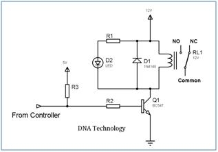 The LED is used to indicate that the RELAY has been turned ON. The resistor R1 defines the current flowing through the LED thereby defining the LED’s intensity.
Resistor R2 is used as a Series Base Resistor to set the base current. When working with 8051 controllers I have noted that it’s not compulsory to use this resistor as the controller has internal 10k resistor which acts as a base resistor.
Microcontrollers have internal pull up resistors hence when a port pin is HIGH the output current flows through this internal pull up resistor. 8051 microcontrollers have an internal pull up of 10KΩ. Hence the maximum output current will be 5v/10k = 0.5ma. This current is not sufficient to drive the transistor into saturation and turn ON the relay. Hence an external pull up resistor R3 is used. Let us now calculate the value of R3.
 Normally a relay requires a pull in current of 70ma to be turned ON. So our BC547 transistor will require enough base current to make sure it remains saturated and provide the necessary collector current i.e. 70ma. The gain (hfe) of BC547 is 100 so we need to provide at least 70ma/100 = 0.7ma of base current. In practice you require roughly double the value of this current so we will calculate for 1.4ma of base current.
For more detail: Interfacing Relay to Microcontroller Schematic
Current Project / Post can also be found using:
- I2C to USB pic
- Proteus I2C simulation steps using pic18f
The post Interfacing Relay to Microcontroller appeared first on PIC Microcontroller.