Quantcast
Channel: Interfacing(USB - RS232 - I2c -ISP) Projects - PIC Microcontroller
Viewing all 320 articles
Browse latest View live

TD-USB-01 interface with mouse sensor board using PIC18F2550

$
0
0

This is an example USB project showing how to interface an optical mouse sensor (the ADNS-2620) with a standard XP/Vista computer.

The TD-USB-01 board with a PIC18F2550 communicates with:

  • the PC: USB 2.0 through a mini-B connector.
  • the mouse sensor board: SPI over 4-wire flatcable.

mouse sensor board


Here are the technical specifications:

  • PC Win XP/Vista interface application with Visual C# 2008 Express: free download.
  • TD-USB-01 (green pcb on top) with PIC18F2550 USB HID setup.
  • Mouse sensor board (046) with ADNS-2620.
  • USB Bus powered, no external power supply needed.
  • ADNS-2620 registers selection stored in the windows registry.
  • Refresh rate from 1mS up.
  • Data bits & bytes details.
  • Real mouse functionality.
  • Sensor CCD 324 pixels: image displayed: 18×18, 6-bit greyscale.
  • TD-USB-01 software is 100% upgradable with a simple RS232 bootloader.
  • RS232 interface for raw data readings.
  • PCB Dimensions: 40 x 41 mm or 1″57 x 1″61

These assembled boards are available from our online shop.

Source code (CCS C and Visual C#) can be purchased separately.


Sensor example Source code (CCS C) , sensor board pcb layout and schematics (Eagle) available. 

Last update: March 28, 2009.

Sensor Board (046): Eagle PCB layout: 046_v002.brd  – Jan. 31, 2009.

 Sensor Board (046): Eagle Schematics: 046_v002.sch  – Jan. 31, 2009.


 ADNS-2620: CCS c source code: optical_mouse_v03.c  – March 27, 2009.

 TD-USB-01:Hex file: 046_v003.hex bootloading for the PIC18f2550  – March 27, 2009.

 Windows interface application setup: 046_app_setup.zip  – March 27, 2009. Written in Visual C# 2008 Express, compatible with Windows XP and Vista.


For more detail: TD-USB-01 interface with mouse sensor board using PIC18F2550

Current Project / Post can also be found using:

  • transducer working projects

The post TD-USB-01 interface with mouse sensor board using PIC18F2550 appeared first on PIC Microcontroller.


Low cost LCD module interface with optional LED backlight using PIC18F452

$
0
0

Here are the technical specifications:

  • LCD resolution: 128 x 64 pixels
  • LCD manufacturer: DisplayTech.
  • LCD model 1: 64128COG-FA-BC (no backlight)
  • LCD model 2: 64128G-FC-BW-3 (white LED backlight)
  • On-glass lcd controller KS0713, with 30 pins connector.
  • Very low power operation (less than 1mA @3V)
  • Fast serial interface (only 8 wires needed)
  • Molex miniature connector.
  • LCD: dimensions: 56 x 41 mm
  • PCB interface: Dimensions: 44 x 18 mm

LCD module


These two LCD modules can be bought in our online shop. You’ll need the interface described below and a PIC microcontroller to get these LCD modules running.

PIC example Source code (CCS C) , pcb layout and schematics (Eagle) available.  Last update: March 24, 2007.

PIC software example: routines

ccs routine example explanation
LCD initialization dt_lcd_init(); init parameters needed after power on
Clear screen dt_lcd_clear_screen(); resets all pixels, needed after power on
Cursor position set dt_lcd_gotoxy(0,5); goto cursur location x= 0..127 PIXEL COLUMNS // y= 0..7 CHAR. ROWS
Write text to LCD printf(dt_lcd_printchar,” DisplayTech LCD”); show simple unformatted text


Downloads: right-click & save as

Interface: Eagle PCB layout: 042 – 004.brd  – March 24, 2007.

 Interface: Eagle Schematics: 042 – 004.sch  – March 24, 2007.


 PIC CCS example: source code: 042_v01.zip for 18f452 @ 20MhZ – March 24, 2007.

 PIC CCS example:Hex file: 042_v01.hex for 18f452 @ 20MhZ – March 24, 2007.


For more detail: Low cost LCD module interface with optional LED backlight using PIC18F452


The post Low cost LCD module interface with optional LED backlight using PIC18F452 appeared first on PIC Microcontroller.

Electronic door codelock with PIC

$
0
0

description

This is my electronic codelock to use with an outdoor gate. The lock itself is implemented in software. It operates a relay (for example to open a door) for a few seconds if someone enters the valid code. The secret code can be changed any time after entering the current code. Note that in this application it’s not necessary to make an exact clock frequency with crystal (as seen on the schematic diagram), you can also use an RC type oscillator or other crystals.

I have the codelock design on my webpage for long and it is really poular. But it had some weaknesses like source code complexity, it needed an external 74LS138 and diodes because it was built on a general protoboard. Therefore I totally rewrote and redesigned it with simplicity in mind. The old design is still available here.

software

The version 2 codelock software has cool new features:

  • low power consumption due to keyboard wake-up
  • stores the code in the internal DATA EEPROM
  • the length of the code is user definable (actual is 4 numbers)
  • the running frequency is adjustable (actual is 10MHz)
  • output pulse width is adjustable (actual is 3 seconds)
  • code can be changed any time

The source code is freely downloadable. This is written for the PIC16F84, but you can easily adapt it to newer controllers like the 16F628, OTP versions with or without internal EEPROM. The first few lines contain the definitions of changeable parameters. If you are lazy, here is a compiled HEX file of the source intended to use with 10MHz crystal and P16F84(A). The codelock will work fine regardless of the actual frequency (the crystal you use) of PIC running, but the timing loop is calibrated to the frequency defined in the code (10MHz)

Electronic door codelock with PIC Schematicoperation

The keyboard, which is organized into a matrix looks like this:

COL0 COL1 COL2 COL3
ROW0 1 2 3 A
ROW1 4 5 6 B
ROW2 7 8 9 C
ROW3 * 0 # D

You can use a 3×4 keyboard as well, because column 3 is not necessary in this application. # is used as ‘enter’ after you type in the valid code. The initial code is 1234 after programming the original source. You could activate the output with typing in:

1 2 3 4 #

* is used to change the code. Type in the actual code then press *. If you didn’t miss the actual code, the code change indicator LED will light up. Then type in the new code twice. Eg:

1 2 3 4 * 1 9 9 8 # 1 9 9 8 #

will change the code to 1998. The code changes immediately and permanently after typing the new code twice. If you miss entering the new code twice, the original code is kept.

If you don’t want anyone to be able to change the code, you can replace the ‘*’ key in the keytable to ‘#’. Or you can place the 3rd column inside your lock and use a key in this column coded ‘*’ to change the code. If you loose the actual code, you will need to access the DATA EEPROM of the controller with a programmer. The code can be read out or rewritten by the programmer.

posted by Pokas on 2003-03-19 23:44
Not work.
(list p=16f84
#include <p16f84.inc>
mhz EQU D’4′),MPASM
Why?


posted by Pokas on 2003-03-19 23:26
Nedirba.


posted by dev on 2003-03-14 07:27
i am final year engineering student(ECE Dept)
we are doing a project in PC Based Oscilloscope.
We Need details of ADC 0804,LM 3914,LM 324,CD 4016,74244,7805
Expecting details from U.


posted by Stefan on 2003-03-13 19:22
Sorry!
Forgot the url to the schematic!
It’s not the best but hopefully you will understand. Atleased the pins we use are shown.
The url is: http://lisbeth.3fas.com/~mammuth/schema.jpg/Stefan


posted by Stefan on 2003-03-13 19:00
Can somebody please help!
New to this. I need help fast.
I need pic hexfile for a goldcard (pic16F84A & EEPROM 24LC16) that should send out a code when it gets power. Then I have a ic: pic 16F84, which i also need the hex-file for. This ic should recieve the code on one pin and if it’s the right code, it should send out a signal on another pin for 10 seconds. If it’s the wrong code it should do nothing. We will then use the outsignal in a transistor to close a circuit, like a relay.
The schematic we got is on:
Please help us, it is a school assignment that should be finished very soon. We thought we would make it but it seemed that assembler whas to hard for us. Please help us with the source, we will read it and probably learn something from it.
You can contact me either on steffoponken@hotmail.com or ICQ: 14489649/Thanks in advance
Stefan


posted by mohsen on 2003-03-13 09:06
please send for me additional information such as block diagram,circuit diagram blockdiagramfor code, component and any information about this project. thanks.


posted by Ernie on 2003-03-12 15:41
Hi everyone.i m studying alone electronics and i have just begun studying the pic microcontroller.if someone has this program for the pic i would be greatfull because i need a good example in order to understand a few things.it would also be good if u also sent some other URLs about electronics etc.Thank you.
ernieraz@hotmail.com


posted by ahmad daqamseh on 2003-03-11 12:32
dear sir
iam a stuedent and i would you like to send me component and the diagram or the circuits of the door codelock on my e mail quickly.
thankyou


posted by moorthi on 2003-03-11 12:09
the circuit is very nice


posted by DeLiMaVi on 2003-03-10 16:20
Thanks…..Best

Turkey/Istanbul/Bagcilar


posted by fucker on 2003-03-10 06:10
this is the best item


posted by prashant on 2003-03-07 12:11
hi friends,
i am doing my graduation in electronics engg.. I am from india .i really need
your help.actually we have to do project in last yr of this cours.and i am searching for it if u have any idea related to micro processor based or related with robotcsORrealated with control panels then pls mail me on
prashantindiain@yahoo.co.in
meetme2@epatra.com


posted by michael on 2003-03-06 21:39
deer sirs,
I am an chinese student.I have made a 89c2051 based code lock,but it could not change password,I can send it to you.I was very impressed by your website.I would be really thankful to you if you could send me a circuit which can define 2 different passwords and one master password.Master Password length is 8 digits and user password length is 4 digits.The master code is use to change user code.Can u plase give me the circuit schematic and the source code ,I need urgently
thank’s your help.
with best regards,
michael


posted by jap on 2003-03-05 12:35
> If i take out the third column will I need to modify the code for the PIC

- no


posted by rah on 2003-03-05 06:16
dear sir
please send me circuit of fingerprint door access system


posted by DTG2003 on 2003-03-04 13:45
Hi i have a really important question to all

How i can read a pic with code protect ?

its really important for me is it impossible to read a Pic 16f628 with Code protect ??


posted by Ian on 2003-02-28 17:29
If i take out the third column will I need to modify the code for the PIC


posted by tufan on 2003-02-24 16:21
&#305; have got pic16f628 in the secret hex.&#305; dont read.
how programmer and software need for me…?thanks.
send my email pls…


posted by jeffrey yik on 2003-02-17 06:04
Hi,
I need a circuit which can define 2 different passwords and one master password.Master Password length is 8 digits and user password length is 4 digits.The master code is use to change user code.Can u give me know what material is use for this project circuit.
I need urgently this circuit schematic.
thank’s your help.


posted by kunal.s.kalyanpur on 2003-02-15 16:15
I am an Indian student.I am currnetly doing a course on 8051 based microcontrollers.I was very impressed by your website.I would be really thankful to you if you could send me a list of some 8051 based projects.I was particularly interested in the automatic door opener and electronic door code lock.I am interested in trying out these projects uisng 8051.Could you please send me the circuit descriptions alone for these two using 8051 if you can.
with best regards,
kunal


posted by mohammad on 2003-02-15 08:26
dear sir
what is different between pic16f877 and pic16f877a?
how to use a/d module of pic16f877.please send to me a source code about
to use a/d module
thank you very much


posted by W.C.S. Ranasinghe on 2003-02-11 07:20
I’m a sri lankan student
i would like to know about more information plece send to my e-mail address


posted by daniel on 2003-02-10 15:39
es muy buena la cerradura si nesecitas los pcb de la placa ya los realise
con gusto lo envio
sin cargo


posted by daniel on 2003-02-10 15:37
es muy buena la cerradura si nesecitas los pcb de la placa ya los realise
con gusto lo envio
sin cargo


posted by markie on 2003-02-10 08:35
hi,
i’m markie and i am an engineering student..actually i want to ask you to pls help me with my project coz i really dont have any idea on what to do…it is an mpu based project..i like your idea of the codelock but it’s seems like is so difficult to do..i hope that you would give me a copy of the codelock coz i would want to do it for my project..
thanx…i hope that you’d be able to help me.


posted by Geoff on 2003-02-06 17:02
In the interests of security, I would suggest that additional measures are emplyed to make this fail-safe. A single failure could cause the relay to operate. An RF field, a voltage transient, or random component failure of the PIC chip could operate the transistor, as could failure of either the transistor or relay. My suggestion would be a watchdog circuit to make this fault tolerant and a triplicated output where you do not have to rely on a single device failure to render this insecure.


posted by jose on 2003-02-05 22:54
i have upgradet your circuit and bilt a new satelite to nasa id a codelock


posted by Amith Singh on 2003-02-04 20:49
Hi
I am a student of electronics in South Africa and will be doing a design project as part of my course. I would appreciate it if i could be supplied with more informatin on this lock and how the explaination of the entire program. Your help will be highly appreciated. Thank you.


posted by mepem@e-kolay.net on 2003-02-02 16:59
Siteniz cok guzel , elektronik devreyi inceledim ve yapiyorum.
tesekkurler….
istanbul / turkey.


posted by mepem@e-kolay.net on 2003-02-02 16:58
Siteniz cok guzel , elektronik devreyi inceledim ve yapiyorum.
tesekkuerler….
istanbul / turkey.


posted by mepem@e-kolay.net on 2003-02-02 16:46
Siteniz cok guzel , elektronik devreyi inceledim ve yap&#305;yorum.
tesekkuerler….
&#305;stanbul / turkey


posted by Muhammad Haider on 2003-01-31 08:22
HI i want a detailed information about pic code lock.
your help of me will be appreciated.
please send me complete information on my email.
iieehaider@hotmail.com
iieehaider@yahoo.com


posted by John on 2003-01-30 07:25
I’m trying to do a similar project with a PIC 16F877 or 16F874 using C language. If anyone can help, please feel free to e-mail me @ AeroSpiner@hotmail.com. Thanks


posted by Xenobius on 2003-01-29 17:32
Hello I have built your circuit and i got a broblem. When i connect it to 12v, the relay switches on and keeps ON !!

and also when i try to change the pic from 10mhz to 4 mhz the led keeps ON !!

also the relay woundt change to its normal stat even if i input the 1234# could you help ? thankyou v much


posted by Jamie on 2003-01-29 15:51
I’m a college student in my final year.
It would be very much appreciated if you could send me complete info regarding this electronic code lock project, it’ll would be very useful.
thanks again


posted by D.V.RAJENDRA on 2003-01-24 14:26
Great!
what a service you are doing.I wonder when i read your e-mails.
Can you suggest to a person who knows noting in electronics to become good at making products by using your help.


posted by Emmanuel-lyn on 2003-01-23 17:28
hello! im just wandering if this electronic codelock can be used as codelock for intercom. I hope you’ll find time to answer or explain this to me. Thanks and more power!


posted by sanza on 2003-01-23 05:24
Hi!
im interisted with your project electronic door codelock, can this project be use in many doors? i mean, using a single project into a multiple doors with deffirent codelocks? can u show me a program of it? im confused with it….


posted by sanza on 2003-01-23 05:02
hello
may qouastion
can i use of this source code for pic16f84 with 4MHZ at circui?
plase you send me source code with ferquancy pic of type 4MHZ
thank you .


posted by joshua on 2003-01-22 08:17
Hi,
I’m trying to add this electronic door codelock as another feature in my project.Do u think how I can combine this circuit with another circuit…and can u provide me the layout,please.thank u.


posted by AIT TIMELLOUINE MOHAMED on 2003-01-21 12:18
J’ai l’honour de


posted by AIT TIMELLOUINE MOHAMED on 2003-01-21 12:10
J’ai l’honour de


posted by John Paul Aguiling on 2003-01-20 22:25
Hi! Thanks for posting the codelock combination. I hope you can send me more projects you have done. May be we can share PICs projects…


posted by dexter on 2003-01-19 09:56
Hi!
im interisted with your project electronic door codelock, can this project be use in many doors? i mean, using a single project into a multiple doors with deffirent codelocks? can u show me a program of it? im confused with it….


posted by steve on 2003-01-15 23:04
HI
i work for a company that uses plant machinces and other people keep using them so Would it be easy to convert this to a immobiliser like the code is entered then the realy diables the plant machine and them renter the code to turn it back on


posted by Liz on 2003-01-15 15:47
dear sir,

i’m a computer engineering student from the philippines. We are very much in need your help… We have this project in one of our subjects and we proposed a password enabled door. Our project would enable the user to enter a password and if he makes 3 consecutive mistakes, the door would lock. How will we wire the circuit using a parallel port? By the way, we are using Visual Basic… I’m hoping you could give us, if you won’t mind, the complete details of this project. thanks!


posted by jepoy on 2003-01-14 12:45
dear sir,
if i used pic16f84a and a 4MHZ crystal in this project, what are the possible changes i will made? pls email me the source code and hex file of the changes. pls send me.sir if can i have a favor of full detail about the cicuit tnx for all the information about PIC. (yangkees@yahoo.com)jeff


posted by Hari krishnan on 2003-01-13 10:32
please give me information about same feature purely electronic basis


posted by emin on 2003-01-11 02:18
dear sir,
if i used pic16f84a and a 4MHZ crystal in this project, what are the possible changes i will made? pls email me the source code and hex file of the changes. pls send me. tnx for all the information about PIC.


posted by aris on 2003-01-10 03:58
hi sir, im aris a student. i really need your help. i have a project called “automatic door opener using barcode reader” the problem is the serial barcode reader. if we going to use it, is there a tendency that we overcome a multitask? pls. send me a shematic diagram to operate the door and what type of door will be using? thanks


posted by VANILDO on 2003-01-05 21:41
GOSTARIA DE OBTER ARQUIVO BIN/HES PARA PIC16F84A (SKY BRASIL) OU PIC16F876.
AT:VANILDO


posted by sandeep on 2002-12-28 11:58
hello sir,
i’m sandeep from india and i’m doing my bachelor’s course in electronics.i need to make an elec lock as a part of my project.it should be suitable to me.i’ve written a program in ‘c’ language & acc to it a person with a correct password can enter the office etc.i need a lock circuit that connects the serial port of the PC to enable my project.so kindly give me the details of the reqd circuit as soon as possible with all details.i’ll be very grateful if u help me out


posted by jepoy on 2002-12-22 16:13
dear sir,
if i used pic16f84a and a 4MHZ crystal in this project, what are the possible changes i will made? pls email me the source code and hex file of the changes. pls send me. tnx for all the information about PIC.jeff


posted by Jean louis tisambi on 2002-12-20 14:22
Hi..
I think that you can help me. We are working in the school project about electronic kill switch for a jeep. This kill switch has a keypad where you can enter pin number. If you enter three times the wrong number the system will be desabled and activating an alarm. In my group studends that should prepare the program they did program and in the circuit it does not work. So we decide now to use PIC microcontroller insted of 8031. I start writing my program but I am not sure to get it in few time because I just learn the PIC now, I do not have understood very well everything on PIC. I need your help if I can get something from you.
Maybe you find some orthograph error because my fisrt language is french.


posted by obing on 2002-12-16 14:31
ansaya saya!!!


posted by orimoyegun peter akinyemi on 2002-12-16 13:57
sir, I’m a student of ECE,lagos state university. I would like you to send me the full details of the circuit,program for the processor and other related informations. I am a 400level student and would like to use it for my project.


posted by bit_zero on 2002-12-14 08:57
can i have a copy too of the schematics and details and the .asm files,,,, i need ‘em for my project….thanks and hey to peeps from the philippines…


posted by sadan on 2002-12-13 07:54
Fine, and kindly add some more projects with 8051/pic 16f84

keep the ball rolling

with regards
sadan


posted by R@j on 2002-12-12 10:31
Yello, how r u? I am fine. How was the party last nite?I am making a circuit board for my gcse’s. So far, I have 1 circuit board. I am supposed to have about 5. This circuit board that I am using, involves the 7225 chip.Can u give me some circuit boards which is for an electronically accessed safe. Remember I your friend. Thanks. R@j


posted by Adam on 2002-12-10 21:17
Dear Sir,

I am currently working on an alarm project in which i plan to incorporate your door lock circuit. I have the 20mhz version of the PIC. Can you please email me with details of what i need to change as I have limited knowledge of PIC’s.

Thank you very much.


posted by Rene on 2002-12-10 08:22
hi sir. i am an eng’g student here in the philippines. i’m doing a project proposal using 16F84A microcontroller. i am interested in your e.door codelock. can you include in your website the program you used to your e.door codelock. are all the materials you used available here in the philippines. thanks am lot.


posted by Jessie on 2002-12-08 01:42
Dear Sir,
i am a computer engineering student in the philippines. i am interested about your codelock project ,can i request the details on its materials and program.
i want to make one for my house. thank you very much.


posted by Benjamin on 2002-12-05 14:48
Por favor necesitaria saber si el circuito es posible tener varios codigos para distintos usuarios=?


posted by Sia Ying Foong on 2002-12-03 05:08
hello,i’m a third year student..and i’m going to do my first project….and i’m attract with your door code lock system..can you send me a details about this project..include the programming…and some circuit out there….

hope u can help me…


posted by jeffrey on 2002-12-02 18:30
Sir,,

thank you for sharing this kind of circuit.I’am a ECE student here in the phillipines. it is a big help in my project. i have made your codelock
wireless. thank you! thank you!thank you! thank you!thank you! thank you!

Jeff
philippines


posted by Mark on 2002-11-26 13:30
Thenks for the door lock I have just bilt it so as my 4 year old son can not open our Electronic gate and it works grate


posted by Arnold T. Caluza on 2002-11-25 04:20
Sir,

i would like to have some information about your design: electronic code lock.

specially the schematics and software of your design, i’m an Ece students her

in the philippines. we need to have a design on our microprocessor subject.

luckily i found your design on the net. PIC168F84 is too expensive, and we dont

have any universal programmer to use to decode the program. I would like to ask

if thier’s any microprocessor or microcontroller based project that you can

suggest. And i would like to know if the PIC16F84 has a built in program?

respectfully yours,

ARNOLD T. CALUZA
SJTCP- PHILIPPINES


posted by marciano on 2002-11-21 02:23
can u give me just a simple project, an electronic toy


posted by Ali Ortakabakci on 2002-11-14 22:08
Hi i’m Ali From Turkey i will try it circuit but i don’t know english well
have u e-mail address Mustafa Deniz and Ersin Yücel May u send to me its Thanks


posted by zack on 2002-11-13 19:03
hi!i really need your help to do my thesis.i’m using PIC16F84.i hope u can e-mail any details about any project that u think is good for thesis using that PIC.thank u very much.i need it as soon as possible.


posted by jay-r antonio on 2002-11-07 16:26
hi jap!!

i like ur design about electronic codelock using pic.. can i know the program of these circuit on how will it respond?? thanx very much!!

more power!!


posted by Tom on 2002-11-06 02:42
This is a neat website, im impressed. I think ill build one of these next chance i get


posted by chyke on 2002-11-05 14:35
Please,I am an Electrical/Electronics Engineering student in a university here in Nigeria.
I am supposed to carry out a project on a related topic(E/E related topic of course).
Please give me a proper circuitry breakdown.
Thanks.


posted by Evandro on 2002-11-04 02:25
help i need schematic


posted by Pham Thu Hien on 2002-11-02 08:41
Hi every body!
I have to make an electric lock but I dom’t know where to begin. Can u help me from design the circuit? Please mail me, my e-mail is: mulan20vn@hotmail.com
Thanks a lot!


posted by Pham Thu Hien on 2002-10-31 13:47
Hi everybody!
I’m a student of Hanoi University of technology. Now I’m studying at Electric and Communication Department. My teacher asks me to make an electric lock but I don’t know where to begin. Can you help me from making the circuit?


posted by Law Chi Hang on 2002-10-31 10:57
Dear Jap,

I am a part-time evening student of High Certificate in Electronics and Communication Engineering, in Hong Kong. My lecturer of Project requires us to make a project that use 8051 microprocessor to control the all functions. I decide to make a electronic code lock. It is similar to your design but it is controlled by 8051 microprocessor, not the PIC chip. Unlucky, I am studying a subject of Microprocessor Engineering at initiation. That means my understanding of 8051 assemble program is very weak. I really hope that you can give me some assistance and design concept and assemble program help.

My proposal of the electronic code lock is as shown below:
The electronic code lock system is controlled by an assembly program in an 8051 microcontroller. The program can identify 3 (or more) sets of password, permit 3 times incorrect password input, has the master reset code and has a period control function.
Password and code length can be also changed any time through the k


posted by fraser on 2002-10-29 17:45
well hi if anyone has an old gcse electronics project on a burglar alarm involving a pic please could someone send it to me because i am having real trouble thanks


posted by vinod.kulkarni on 2002-10-28 05:28
Hi everybody,
I want one help from u people,I am trying to operate the 16f877 pic mc for 10 bit adc mode,but it is working like 8 bit only i don’t what the problem,can u anybody help me in solving this problem ,my emailid is vnd2001@yahoo.com
vinod
posted by Vinod.Kulkarni on 2002-10-28 05:26
Hi everybody,
I want one help from u people,I am trying to operate the 16f877 pic mc for 10 bit adc mode,but it is working like 8 bit only i don’t what the problem,can u anybody help me in solving this problem
vinod
posted by david falzon on 2002-10-27 16:08
hi
my name is david and i am from malta. i am seeking a car alarm circuit working at 12V dc and havin the transmitter to swith it on and off. if you can supply me with the schematic you have given me the greatest help that you imaginethanks in advance

david

posted by Fatih on 2002-10-25 15:25
Hi… I will try to run your circuit in ISIS Proteus5.2. But I don’t run it.
can circuit’s asm cod be to absence? can you help me pls?


For more detail: Electronic door codelock with PIC

The post Electronic door codelock with PIC appeared first on PIC Microcontroller.

PIC18F452 to PC USB 2.0 interface with FT245BM

$
0
0

Here is an example of how to interface a PIC18F452 to a PC  via the USB port.

The windows-pc (98, Me, 2000, XP, 2003) runs a program (C# application, Microsoft Visual Studio .NET 2003) to communicate with the USB interface, which transfers data to and from the PIC18F452.

Many thanks to FTDI to deliver royalty-free drivers (FTD2XX.dll) and to KOPF to develop the needed library (AID.dll)

All parts are available in our online shop.

Schematic (Eagle 4.11e), PIC source code (CCS) , PIC hex file, C# code and application available for download.


Circuit explanation:

PIC example (18f452) < > USB interface (FT245BM) < > PC program (C# application)

PIC example (18F452:)

The PIC captures the ambient temperature with a SPI sensor TC77. Its value is then transferred to the USB-interface.

 FT245BM

USB interface (FT245BM:)

The USB interface will have to be recognized as a device by Windows. Basically, there are two ways of doing this. Either with a VCP (Virtual COM Port) or with a D2XX (Direct) driver. We will use the D2XX driver here for its high speed. It is more complicated to start up than VCP, but why not going the extra mile?

The FT245BM chip comes with a fixed VID (0403) and PID (6001). We can override this with our own VID (ECDE),  PID (0001), our own Product Description (TechDesign USB Device 017) and serial number (FEDC0001). These settings are stored in an  external SPI EEPROM 93C46. To program these settings, FTDI made a utility called MProg EEPROM programming utility.

When plugging in for the first time and with a blank (or without) EEPROM, you will notice that the interface is seen as “USB device” and after its driver is installed, it will be recognized as a “FTDI FT8U2XX Device”. Now we can program the EEPROM with our custom settings. To do this, run MProg, open the file 017_USB_id.ept and program (choose “Device”, then “Program”). After this, unplug the interface briefly and plug it in again. It will now be recognized as a  “TechDesign USB Device 017″. Acknowledge a couple of times to install it and you are done.

Note that this project will also work without an EEPROM, but in that case you will have to make do with the fixed VID & PID.

PC program (C# application:)

A dll file is performing the communication between the C# application and our USB-interface. It must be placed in the same directory as the exe-file below. Acknowledgements to KOPF for providing this dll and the example “USBTransfer.exe” on which this application is based.

The C# application can be run on any Windows 98, Me, 2000, XP, 2003 platform. It will show the temperature reading captured with the PIC (see above). Here is a quick link to its main form. Download the msi (Microsoft installer file) below to install the application.

You need to have Microsoft .NET Framework 1.1 (or higher) installed to be able to run the executable.

For more detail: PIC18F452 to PC USB 2.0 interface with FT245BM

Current Project / Post can also be found using:

  • pic18f452 pll ccs pic program

The post PIC18F452 to PC USB 2.0 interface with FT245BM appeared first on PIC Microcontroller.

MICROCONTROLLER BASED INTERFACE UNIT FOR 5KW MICROWAVE OVEN

$
0
0

1. Introduction

Microwaves are maybe, one of the greatest discovers of the 20’th century. With a vavelenght between 30 cm and 3 mm and a power between 1 mW and 500 KW are practically used in all fields from medicine to industry. Microwave thermal and chemical tratments are well known for the high efficiency, with 3 to 1000 times greatest then conventional process because of direct energy transfer into materials and selectivity compounds heating following dielectric permittivity parameters of the materials involved in reaction or in the treatment (equation 1):

where: - e is the real part of the permittivity, which characterize the amount of microwave reactive power changed with material (without absorption);
- e’’eff is the imaginary part of the permittivity, which characterize the microwave global absorption’s in the material.

MICROCONTROLLER BASED INTERFACE UNIT FOR 5KW MICROWAVE OVEN The permittivity is a function of the material temperature and of the microwave frequency. In the general case, the permittivity is a tensor which depends on the homogeneity and anisotropy of the materials. The microwave power absorbed in the material, assuming that all microwave power is transformed in warmth, is (equation 2):

Any microwave oven is a multimodal microwave cavity in which the incident power ( usual 700W to 70KW at 2.45 GHz ) has a particular distribution . If the probe to be treated has a great volume ( like drying foods in foodstuff industry or ceramic materials microwave drier ), this multimodal cavity is suitable for a treatment because many parts of the local power distribution are intersecting the probe volume. The user must have a total control for the microwave radiation like: modifying continuously the output power in a large range ( not only the output energy used in almost all home-appliance ovens ) and controlling precisely the treatment period.

We present here, briefly, our design concerning a 5KW magnetron oven with an effective volume of 1 cubic meter, based on continuous wave CK 101 magnetron and driven by a flash microcontroller PIC16F877.

2.The concept
In fig.1 is shown the typical structure for our high power microwave oven:

Fig.1 Typical high power structure of a microwave oven -

The magnetron ( microwave power generator ) is supplied through an anodic transformer ( T1-6KV/1A ) and a two steps filament transformer ( T2-7.5V/42A and 5.5V/36A ). The magnetic field of the magnetron is produced in two coils ( L1 supplied from a PWM based constant current source, with max.10A and 20V voltage swing and L2 supplied by a feedback anodic current ).

MICROCONTROLLER BASED INTERFACE UNIT FOR 5KW MICROWAVE OVEN SchematicAll supplying algorithm are supervised by microcontroller board (4) with a simple interface user (6) consisting in four functional buttons ( the same buttons have different functions displayed on the second line of the LCD as the program flow chart required) and a large LCD display. Because the high anodic temperature ( 150 C ), a cooling system ( with cold water and air flow ) is required. Both the water flow command and air flow presence are supervised by the microcontroller board using an anodic temperature measurement. All other parameters like door status ( open or closed ), cooling water pressure, treatment period and output microwave power are also under microcontroller control.

3. The firmware
The firmware is a software translated into a hex code by a compiler [3] or an assembler and stored in microcontroller’s [1] memory by a programming sequence, assisted by the PC and by a hardware programmer [5] board. A bootloader [2] will allow fast low voltage programming as many time as the firmware development is requiring. For our oven, there are 14 different LCD screens,


For mre detail: MICROCONTROLLER BASED INTERFACE UNIT FOR 5KW MICROWAVE OVEN 

The post MICROCONTROLLER BASED INTERFACE UNIT FOR 5KW MICROWAVE OVEN appeared first on PIC Microcontroller.

Microcontroller Adc Project Circuit

$
0
0

The microcontroller projects resources., Pic microcontroller tutorials, resources and projects ranging from simple to advanced designs with schematics and source code. free for non-commercial use..

Microcontroller Adc Project CircuitRelated Article Microcontroller Adc Project Circuit :

Microcontroller Adc Project Circuit SchematicRelated Video Microcontroller Adc Project Circuit :

 Watch Avr atmega microcontroller tutorial 4 blink led( tishitu online
Microcontroller project ideas and electronic circuit project ideas based on pubilc doman patents – some of the best minds in history!…

Watch Analog to digital converters | a to d converter online
Pic microcontroller tutorials, resources and projects ranging from simple to advanced designs with schematics and source code. free for non-commercial use….


For more detail  Microcontroller Adc Project Circuit

The post Microcontroller Adc Project Circuit appeared first on PIC Microcontroller.

Isolated RS232C for PIC16F84

$
0
0

Another method that helps program development besides a dot LED as the output device is a serial bit. With a serial transmission to a terminal emulator program, developer may then test program running easier than a dot LED. One of my circuit uses PIC16F84 having one bit for sending ascii character with “printf” function. The PIC16F84 provides a very convenient way of connecting serial data to terminal. We may use a 1K resistor connects RB1, say to RxD pin of COM1 directly.

Isolated RS232C

As shown above diagram, my PIC circuit uses a transformerless DC supply. Direct connection is then not recommended for safety. The ground voltage difference between two circuits may destroy the RS232 converter chips. We thus need an isolation device to separate AC line and notebook circuit. The example circuit for PIC16F84 shown below, uses RB1 as a TxD pin. Digital baseband is NRZ, i.e., data bit 1 is logic high and data bit 0 is logic low. The heart of the circuit is a 4N26, an opto-isolator with NPN output transistor. Since the output port of the 16F84 can drive LED directly, say with sink current. We need only a 180 Ohms current limiting resistor connected to RB1.


For more detail: Isolated RS232C for PIC16F84

The post Isolated RS232C for PIC16F84 appeared first on PIC Microcontroller.

A Minimal USB CDC ACM aka Virtual Serial Port

$
0
0

This page introduces a minimal firmware that implements a USB Virtual Serial Port for Microchip PIC18F4550 processor.

The code has been optimized to use minimal amout of memory (both Flash and RAM) and tuned to work well with the Free SDCC C-compiler.

The code size is less than 2500 bytes and it requires about 230 bytes of RAM memory and it is capable of transferring almost 1 MB/sec (if only the PIC could generate any data at that speed!).

Why Virtual Serial Port

One of the hurdless that faces anyone who wants to interface a modern PC with the real physical world is the fact that most new computers have neither a serial port nor a parallel port that could be utilized to interface with external world. Most come only with USB and Etherner connections.

While USB standard is realy not that bad once you get into grips with the basics, it can be very intimidating. To make matters worse using USB often requires writing device drivers which can be even more intimidating. If you want to support the most common operating systems, Mac OS X, Linux or Windows, the task just gets bigger, easily beyound the resources of a lone developer.

But if you make your device appear as virtual serial port then the drivers will be provided by the courtesy of the operating system ie all the operating systems have built in drivers for serial ports.

A Minimal USB CDC ACM aka Virtual Serial Port True, there are libraries, I especially want to mention libusb , which make it relatively easy to access and develop a class of USB devices without writing drivers. And libusb is cross platform which I like a lot. Still it is an other dependency for your project and requires a native library to be linked with your host side application which is more work if you want to do cross platform application development with languages like Java, as I do.

Serial ports are easily accessible from various programming languages including C/C++, Python, Java, VisualBASIC etc.

Using the CDC ACM library

It sounds a bit grand to call this a library when in reality it is just one source code file and a three files with USB related ‘#define’s. I’ve created a ready to compile sample project that implements a virtual serial port that just echoes back everything you send to it. You can download the source code from here.

A word of warning about the source code: it was taken from a project that is fully functional but I had to clean it up a bit and remove some personal stuff. It compiles and there is a high probability that it works but I have not had the time to test it after the clean up. If you find any problems, please let me know.

Prerequisites

In priciple you should obtain your own PID and VID for your device from the USB consortium (or more easily from Microchip) but for simple testing and development it is ok to use what I have in the code ie Vendor id = VID = 0x0408 and Product id = PID = 0x000A.

To use the library you need to have ‘GNU autotools’ and ‘SDCC’ installed and in your ‘path’. You can of course compile the code without the autotools as there are just half a dozen files to compile. To program the firmware into the device you need the Microchip PICKit2 programmer and the ‘pk2cmd’ software that supports it on the ‘path’. If you don’t have the PICKit2 you realy should get one, at USD 35 it is a steal and it is supported on Linux, Windows and Mac OS X.

And naturally you need a PIC18F4550 device with 4 MHz xtal. It is also possible to use the other PIC18F series devices and crystals but some changes to the link and config options maybe necessary.

Compiling

To compile the code unzip the project into a directory and just cd to the directory where you have the code and type make. This should compile the code and program it to the device if you have the PICKit2 in readiness. The object code and resulting hex file will be placed in a directory obj parallel to the source directory.

Testing

To test it you need a terminal emulator. Plug your device to the USB port, open the terminal emulator, select the correct port and everything you type should be echoed back to the terminal.

Testing on Mac OS X

In Mac OS X type ls /dev/tty.usb* to get a list of USB virtual serial ports and then use the built in screen terminal to talk to it.

For example:

ls /dev/tty.usb* /dev/tty.usbmodem5d11 screen /dev/tty.usbmodem5d11

Testing on Linux

In Linux type ls /dev/ttyACM* to get a list of USB virtual serial ports and then use the built in screen terminal to talk to it.

For example:

ls /dev/tty.ACM* /dev/tty.ACM0 screen /dev/ttyACM0

Testing on Windows

In Windows you need to install an .inf file that will associate your device with the built in driver.

To install the ‘driver’ plug in the device and go to the Device Manager. Look for an ‘Unknown device’ and select ‘Properties’ for that device, then select ‘Install Driver’, browse to the cdcacm.inf file which is included with the project files.

Note the file has not been tested after clean up so there maybe some errors.

Also note that if you change the PID/VID of the device (and in the long run you should) then you need to update the cdcacm.inf file and re-install it.

After succesfull installation the device should appear as a COM port and you can use a terminal emulator such as PuTTY or TeraTerm to talk to it.

// send six bytes ie 'Hello\n'
   while (usbcdc_wr_busy())
      /* wait */;
   cdc_tx_buffer[0]= 'H';
   cdc_tx_buffer[1]= 'e';
   cdc_tx_buffer[2]= 'l';
   cdc_tx_buffer[3]= 'l';
   cdc_tx_buffer[4]= 'o';
   cdc_tx_buffer[5]= '\n';
   usbcdc_write(6);
   }

Understanding the Library

The library realy is simple to use, basically there are two functions and two buffers for transferring the data in and out of the device, there is a function that needs to be called periodically to poll the USB bus, there is a function to initilize the library and auxiliary functions to implement standard putc/getc functionality.

Note that the library code is written from the device point of view, ie ‘tx’,’put’ means that the device sends something to the host which maybe confusing because on this is called ‘input’ direction in USB terminology and the host code would use ‘read’ functions to receive the data. Just thought I’d mention this.


For more detail: A Minimal USB CDC ACM aka Virtual Serial Port 

The post A Minimal USB CDC ACM aka Virtual Serial Port appeared first on PIC Microcontroller.


Interfacing Ultrasonic Distance Sensor : ASCII Output with PIC Microcontroller

$
0
0

In some of our projects, we may want to measure the distance of an object from a point. Ultrasonic Distance Sensors are the best sensor which provides stable, accurate, precise, non-contact distance measurements from 2cm to 4m. Ultrasonic Sensors can be used to measure distance between moving or stationary objects. Being very accurate and stable, these devices find large number of applications in robotics fields. For example it can be used as an excellent replacement for IR sensors in  a Micromouse. In this tutorial we will lean to interface an Ultrasonic Distance Sensor with PIC Microcontroller.

Interfacing Ultrasonic Distance Sensor  ASCII Output with PIC MicrocontrollerHere for demonstration we are using Rhydolabz Ultrasonic Distance Sensor with ASCII Output. It can be easily interfaced with a PIC Microcontroller using USART by just connecting the output pin of the sensor to RX pin of the microcontroller. In every 500ms this sensor transmits an ultrasonic burst and listens for its echo. The sensor sends out ASCII value corresponds to the time required for the ultrasonic burst to return to the sensor. The UART of the sensor is operates at a baud rate 9600 and the sensor can be powered by  a 5V DC Supply. The ASCII output of the sensor will be equal to the distance to the obstacle in centimeter (cm).

Interfacing Ultrasonic Distance Sensor  ASCII Output with PIC Microcontroller SchematicThe sensor has three pins…

  • Vcc  – +5V DC Supply to the Sensor
  • GND –  Ground Level of the Power Supply
  • SIG – Signal, Serial Data Out’


For more detail: Interfacing Ultrasonic Distance Sensor  ASCII Output with PIC Microcontroller

The post Interfacing Ultrasonic Distance Sensor : ASCII Output with PIC Microcontroller appeared first on PIC Microcontroller.

Serial Data Logger using PIC16F688

$
0
0

The data logger consists of a simple op-amp amplifier circuit that amplifies the signal and sends it to be digitized by a PIC16F688 microcontroller, serialized, and sent to the computer’s serial port via a MAX232 serial driver:

I guess you are already wondering about some of the unusual arrangmenents in the analog part in the schematic diagram above. Part of it is because of the voltage differences between the analog and digital part: the op-amps work on 12V while the microcontroller and the serial driver require 5V. Part of it is to make the different kind of sensors I plan to use easier to connect. Finally, this is partly because I’m really lazy and when I got the things to work to my satisfaction I refused to change anything. The point is – unusual or not, it works.
Serial Data Logger

Operation The logger has two inputs:

IN1 is a DC-input with a range of 1-11V. Whatever voltage is applied to IN1 is directly passed to the amplifier. Try to keep the voltage centered around the 6V point for best results.

IN2 is an AC (self-centering) input with a range of ±5V. The trimmer potentiometer R1 connected to this input centers the signal at 6V when the sensor signal is not changing.

Switching between inputs is done by shorting the JP1 jumper. You can either use a switch there and do this manually, or wire JP1 into the connectors you use to plug-in your sensors (which is the way I did it).

Before finishing with the input part, notice the optional amplifier OP2 in the lower part of the diagram. Some sensors based on a voltage divider work best when the voltage is split close to the half point – in other words, if you have a resistor/photoresistor bridge and in the particular conditions the photoresistor has 10k? resistance, the signal will be stronger if the other resistor in the bridge is also around 10k?. Use the trimmer potentiometer R10 to set the desired center point. Afterwards, LED1 will switch on and off when the center point is crossed, helping you adjust your sensor correspondingly.

Amplification is controlled by adjusting R4. If you wish, you can use a higher value for this potentiometer – this will give you higher amplification, but at the cost of more noise.

The output from OP1 is passed to the microcontroller through the voltage divider composed of R5, R6, and R7. The voltage divider is here to assure that the signal passed to the analog input AN4 never goes above 5V. Before plugging in the microcontroller, adjust R6 so when the output from OP1 is at it’s top range, the voltage out of R1 is just below 5V.

The PIC16F688 microcontroller digitizes the signal from AN4, applies checksum information and passes the serialized data at 1200 bps to the MAX232 serial driver. From there, it’s just a matter of plugging a serial cable in your computer and running the logger script logger.pl to record the data.


For more detail: Serial Data Logger using PIC16F688

Current Project / Post can also be found using:

  • pıc data logger

The post Serial Data Logger using PIC16F688 appeared first on PIC Microcontroller.

Turntable Photography Equipment using PIC16F84A

$
0
0

A friend asked me if I could build him a device that would allow him to take photos of his products in 360 degrees. That kind of photo is actually an animation that consists of several photos of the same product but from different angles. It means that we need a device that can be controllable and that could take pictures on even intervals.

Photography Equipment

UPDATE: English version of software is now available for download here.

The idea:

As we can see from the picture above, a device called “Turn Photo” controls the digital camera (focus and shutter) and the device itself is controlled by a PC application written in Delphi 7.

All project files are available for download by clicking on the red download button below.

Turn Photo – hardware
Roughly, the device consists of PIC16F628A microcontroller, USB<->Serial PL2303 converter IC, ULN2803A IC transistor array, 2 opto-couplers and one stepper motor. Electronics are powered from USB port, actually from a PL2303 PCB Module, and motor is powered by independent 12V power source.

Two versions of this device were built. The first one was with stepper motor from an old 5.25″ floppy drive TEAC 14769070-90. That is a unipolar motor with 4 coils inside, and it has a resolution of 1.8 degrees per step which makes 200 steps in total per one complete revolution. When we drive it with half-stepping method, it doubles to 400 steps per revolution. A problem with this realization was that I didn’t use gears between the motor and the rotating plate (a circular plexiglass sheet that holds/rotates the product) – it was a direct-drive. A thing to note here is that we need to rotate objects with the smallest speed possible to avoid them dancing all over the plate. So, with a direct-drive and slow motor speed it produced massive vibrations. When motor speeds up – vibrations disappear, but we don’t want it speeding around. After testing and trying to fix the problem by changing stepper motor driver parameters and using dampers I decided to abandon this direct-drive design.

Second version of mechanics (the winning combination) is done by using a stepper motor M35ST-7P from an old HP scanner which was also unipolar with 4 coils but with a much smaller resolution of just 7.5 degrees per step. It means that the motor makes just 48 steps per one revolution. The good thing is that two gears came with this motor and the steps were prescaled by 25 (1:25 gear ratio) which means we now have 360/48/25 = 0.3 degrees per step. Another good thing here is that we can drive it faster because the speed also reduces by 25 x. This solves the vibrations problem totally and now we also have a maximum of 1200 steps or even 2400 with half-stepping per one revolution of final “drive” gear.


For more detail: Turntable Photography Equipment using PIC16F84A

The post Turntable Photography Equipment using PIC16F84A appeared first on PIC Microcontroller.

Pic-Plot2 GPIB to USB converter

$
0
0

Pic-plot now goes to USB! A perfect low cost solution to quickly get screen plots of your GPIB instrument on your laptop PC without complex software. It emulates the HP7470A operation on the GPIB side, and outputs the HP-GL data at the USB port to be read and stored on the PC by any capturing software. GPIB addresses and other set-and-forget parameters can be configured by a simple Setup menu, then no Dip-switches are used. Power is taken from the USB port to simplify cabling and get rid of a DC adaptor.  The operation of this interface is not just limited to digital plotter emulation: any data intended to be received by a GPIB Device (addressable or listener only) can be captured from the instrument and brought out to the USB port, including raw measurement arrays or rasterized data for a graphic printer. It is based on a PIC16F628 microcontroller and an FT232R chip. PCB size is just 57x64mm.

USB converter

SCHEMATIC AND DETAILS

The hardware of Pic-Plot2 interface is quite simple: the active components are a Microchip PIC16F628 microcontroller and an FT232 chip from FTDI. The microcontroller manages the GPIB protocol and signals, while the FT232 does the bridging between the USB and the microcontroller UART. No oscillator crystal is needed because the FT232 provides the 12 MHz clock for the microcontroller, and the 5V needed to supply the whole circuit are taken from the USB host PC.
The microcontroller does all the necessary jobs to emulate GPIB Device functionality, in both Listener and Talker mode, by recognizing addressing, commands and managing the Handshake lines. Controller mode is not needed for the intended functionality, and therefore is not supported. Once the device is addressed and it receives data from the Talker, the same data are forwarded from microcontroller UART to the FT232 at 38400 baud. Then the FT232 manages the USB communication to the host PC where a Virtual COM Port (VCP) has been created by installing the proper drivers. A standard A-B USB cable is needed for data and power connection. There is no power switch: the interface is ON whenever plugged to the host PC.

Two LEDs (LD1-green, LD2-red) respectively indicate:
– Successful bus enumeration
– Data traffic (RX or TX) over USB bus

A small pushbutton switch is provided to enter Setup mode. In this mode the PC is used to read/change a few set-and-forget parameters that are stored in the non-volatile memory of the microcontroller. Even if the GPIB cable can be left connected to the instrument,  in Setup mode the GPIB port is not monitored by the Pic-Plot2. Normal operation is restored at the end of Setup procedure, or unplugging-replugging the interface from the host PC.


For more detail: Pic-Plot2 GPIB to USB converter

The post Pic-Plot2 GPIB to USB converter appeared first on PIC Microcontroller.

How to use inbuilt EEPROM of PIC18F4550 Microcontroller

$
0
0

The EEPROM (ELECTRICALLY ERASABLE PROGRAMMABLE READ ONLY MEMORY) is a very useful memory which can be used for storing data. The data storing and retrieving from any EEPROM memory is very simple compared to other kind of memories. As the name suggest the memory is electrically programmable and hence the data will be sustained in the memory until it is electrically erased or reprogrammed.

There are lots of EEPROM chips available most of them are easy to interface with a microcontroller. It would be even better if the microcontroller itself has a built-in EEPROM. The microcontroller used in this project is PIC18F4550 and it also has an inbuilt EEPROM memory other than the flash memory. The data can be easily stored into or retrieve using simple codes.
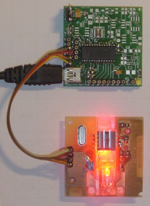
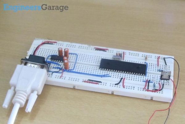
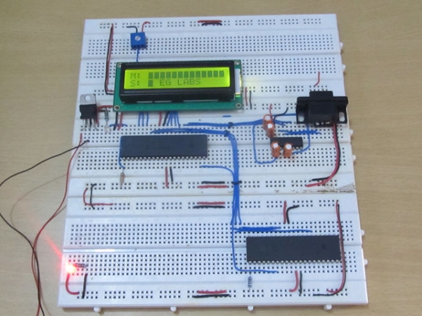
How to use inbuilt EEPROM of PIC18F4550 MicrocontrollerThe project mainly has two parts, a serial communication part and EEPROM accessing part. The data which should be written into the EEPROM is received from the serial port. The internal hardware module USART is used for this purpose. The data which is read from the EEPROM is also send back to the serial port using the same hardware module.

Hence two internal modules of the PIC18F4550 are used in this project namely EEPROM and USART. These hardware modules can be accessed and controller by simply writing into or reading from their corresponding registers.

The important control registers associated with the USART and their details are given below:

TXSTA: TRANSMIT STATUS AND CONTROL REGISTER

This register has the bits which controls the serial transmission features like enable or disable the transmission, whether it should be synchronous asynchronous etc.

For a simple asynchronous serial transmission only two bits are significant, which are TXEN and SYNC

TXEN is the transmission enable/disable bit and SYNC sets the synchronous/asynchronous mode.

TXEN: Transmit Enable

1 = Transmit enabled

0 = Transmit disabled

SYNC: EUSART Mode Select bit

1 = Synchronous mode

0 = Asynchronous mode

RCSTA: RECEIVE STATUS AND CONTROL REGISTER

This register has the bits which controls the serial reception features like enable/disable the serial port, reception should be 8 bit or 9 bit, whether it should be synchronous asynchronous, enable/disable continuous reception etc.

For a simple asynchronous serial reception the significant bits are SPEN, RX9 and CREN.

SPEN: Serial Port Enable bit

1 = Serial port enabled

0 = Serial port disabled

RX9: 9-Bit Receive Enable bit

1 = Selects 9-bit reception

0 = Selects 8-bit reception

CREN: Continuous Receive Enable bit

1 = Enables receiver

0 = Disables receiver

SPBRG: EUSART BAUD RATE GENERATOR REGISTER

This is a 16 bit register into which the value corresponding to the required baud-rate can be written into. The value according to a particular baud-rate can be calculated from the CPU clock frequency according to the following equation;

SPBRG = ((FOSC/Desired Baud Rate)/64) – 1

Where; FOSC is the CPU clock frequency

#include <p18f4550.h>
//======================= chip config ===================//
#pragma config PLLDIV = 1
#pragma config CPUDIV = OSC1_PLL2
#pragma config FOSC = INTOSC_HS
#pragma config USBDIV = 1
#pragma config IESO = OFF
#pragma config PWRT = OFF
#pragma config BOR = OFF
#pragma config VREGEN = OFF
#pragma config WDT = OFF
#pragma config WDTPS = 32768
#pragma config CCP2MX = ON
#pragma config PBADEN = OFF
#pragma config LPT1OSC = OFF
#pragma config MCLRE = ON
#pragma config STVREN = ON
#pragma config LVP = OFF
#pragma config ICPRT = OFF
#pragma config XINST = OFF
#pragma config DEBUG = OFF
#pragma config WRTD = OFF
//======================= chip config ===================//
void tx_data(unsigned char data);
unsigned char rx_data ( void );
void delay_ms ( int delay );
void eeprom_write ( unsigned char data, int address );
unsigned char eeprom_read ( int address );
unsigned char read_address = 0;
unsigned char write_address = 0;
unsigned char write_data;
unsigned char read_data;
unsigned int i=0;
#define FREQ 8000000     // CPU Frequency
#define baud 9600
#define spbrg_value (((FREQ/64)/baud)-1)     // Refer to the formula for Baud rate calculation in Description tab
void main(){OSCCON = 0x72; // set CPU Frequency as 8 MHz
TRISB = 0x00; // Set PORTB as output PORT
LATB = 0xFF;     // Set PORTB high initially (All LEDs on)
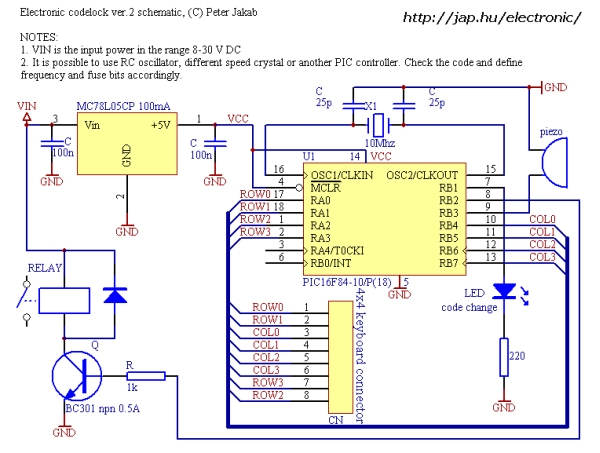
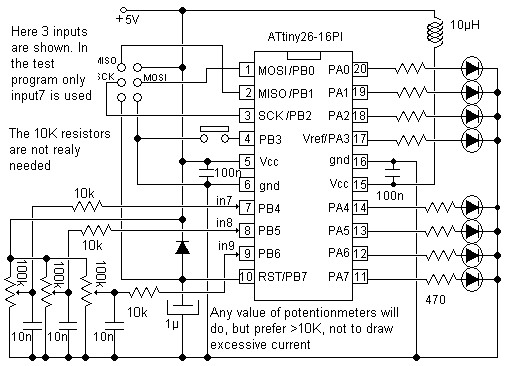
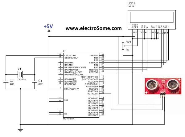
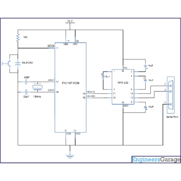
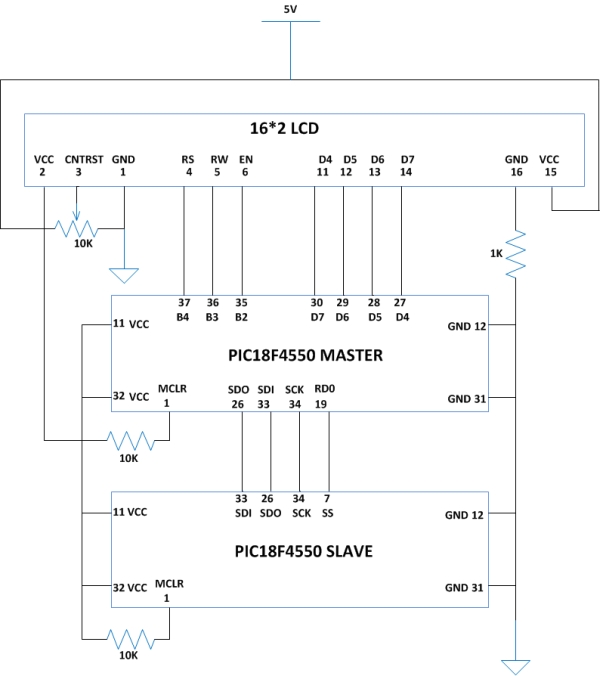
 How to use inbuilt EEPROM of PIC18F4550 Microcontroller Schematic    SPBRG = spbrg_value;                         // Fill the SPBRG register to set the Baud Rate
    RCSTA |= 0x80;                                     // To activate Serial port (TX and RX pins)
    TXSTA |= 0x20;                                     // To enable transmission
    RCSTA |= 0x10;                                     // To enable continuous reception
    while(1)
{   write_data = rx_data ();                     // Receive data from PC
            tx_data ( write_data );                     // Transmit the same data back to PC
            if ( write_data == 0x1A )
            {     delay_ms ( 100 );
              for ( read_address = 0; read_address < 256; read_address ++ ) // read out all the data from 0 to 256
              {                  read_data =  eeprom_read ( read_address );
                  tx_data ( read_data );         // Transmit the same data back to PC
                  delay_ms ( 200 );              }
              while ( 1 );          }
      else          {  eeprom_write ( write_data, write_address ); // store the received data into the eeprom
              write_address ++;          }    }}
void eeprom_write ( unsigned char data, int address )
{
EEADR = address; // wite the required address
EEDATA = data; // write the data
EECON1 &= 0x3F; // EEPGD = 0, CFGS = 0, all other bits are kept unchanged
EECON1 |= 0x04; // WREN = 1, all other bits are kept unchanged
INTCONbits.GIE = 0; // disable all interrupt
EECON2 = 0x55; // should write this value before initializing write
EECON2 = 0xAA; // should write this value before initializing write
EECON1 |= 0x02; // WR = 1, all other bits are kept unchanged
INTCONbits.GIE = 1; // enable interrupts
while ( EECON1 & 0x20 ); // wait till WR becomes 0
EECON1 &= 0xFB; // WREN = 0, all other bits are kept unchanged}

The post How to use inbuilt EEPROM of PIC18F4550 Microcontroller appeared first on PIC Microcontroller.

How-to: Bus Pirate v1, improved universal serial interface using PIC24FJ64GA002

$
0
0

We use the Bus Pirate to interface a new chip without writing code or designing a PCB. Based on your feedback, and our experience using the original Bus Pirate to demonstrate various parts, we updated the design with new features and cheaper components.

There’s also a firmware update for both Bus Pirate hardware versions, with bug fixes, and a PC AT keyboard decoder. Check out the new Hack a Day Bus Pirate page, and browse the Bus Pirate source code in our Google code SVN repository.

improved universal serial interface

We cover the design updates and interface a digital to analog converter below.

The Bus Pirate started as a collection of code fragments we used to test new chips without endless compile-program-run development cycles. We released it in a how-to and used it to demonstrate a bunch of serial interface ICs in our parts posts. This article introduces an updated design with new features and a bunch of improvements.

  • Surface mount design
  • Pull-up resistors on all bus lines with external voltage source
  • Software resettable 3.3volt and 5volt power supplies
  • Voltage monitoring of all power supplies
  • An external voltage measurement probe
  • Cheaper parts

Click for a full size schematic image (PNG). The circuit and PCB are designed using the freeware version of Cadsoft Eagle. All the files for this project are included in the project archive linked at the end of the article.

Microcontroller

We used a Microchip PIC24FJ64GA002 28pin SOIC microcontroller (IC1) in this project. The power pins have 0.1uF bypass capacitors to ground (C1,2). The 2.5volt internal regulator requires a 10uF tantalum capacitor (C20). The chip is programmed through a five pin header (ICSP). A 2K pull-up resistor (R1) is required for the MCLR function on pin 1. Read more about this chip in our PIC24F introduction.

RS-232 transceiver

An inexpensive MAX3232CSE RS232 transceiver (IC2) interfaces the PIC to a PC serial port. This chip replaces the expensive through-hole MAX3223EEPP+ used in the previous version of the Bus Pirate. The serial interface will work with a USB->serial adapter.

The original Bus Pirate has 3.3volt pull-up resistors on 2 pins, but most of our tests required additional external resistors. The updated design has pull-up resistors (R20-23) on the three main bus signals (data in, data out, clock) and the chip select (CS) pin.

A row of jumpers (SV5) connects each resistor to an external voltage supplied through the Vext terminal (X4). Through-hole resistors are used like jumper-wires to make the PCB easier to etch at home.

We couldn’t find an elegant way to control an arbitrary voltage pull-up resistor array from a 3.3volt microcontroller. If you have any ideas, please share them in the comments.

Power supply

VR1 is a 3.3volt supply for the microcontroller and RS232 transceiver. VR2 is a 5volt supply. Both require two 0.1uF bypass capacitors (C3-C6). J1 is a power supply jack for a common 2.1mm DC barrel plug. 7-10volts DC is probably the ideal power supply range.


For more detail: How-to: Bus Pirate v1, improved universal serial interface using PIC24FJ64GA002

The post How-to: Bus Pirate v1, improved universal serial interface using PIC24FJ64GA002 appeared first on PIC Microcontroller.

Interfacing EM-18 RFID Module with PIC Microcontroller

$
0
0

EM-18 RFID Reader Module is the one the most commonly used module for Radio Frequency Identification Projects. It features Low Cost, Small Size, Low Power Consumption and Easy to use. It can be directly interfaced with microcontrollers using UART communication. Software UART can be used for microcontrollers having no UART modules. In this tutorial we will see How to Interface EM-18 RFID Reader Module with PIC 16F877A Microcontroller. By understanding the basic idea, you will be able to interface it with any microcontrollers.

Interfacing EM-18 RFID Module with PIC MicrocontrollerWorking

The EM-18 RFID Reader module generates and radiates RF Carrier Signals of frequency 125KHz through its coils. When a 125KHz Passive RFID Tag (have no battery) is brought in to this field, will get energized from it. These RFID Tags are usually made using a CMOS IC EM4102. It gets enough power and master clock for its operations from the electromagnetic fields produced by RFID Reader.

By changing the modulation current through the coils, tag will send back the information contained in the factory programmed memory array.

Interfacing with PIC Microcontroller

EM-18 RFID Reader Module can be directly interfaced with 5V PIC Microcontrollers using UART module. For 3.3V deviced you need to add additional voltage divider resistors to reduce 5V to 3.3V. You may also use Software UART if a dedicated UART module is not available.

Interfacing EM-18 RFID Module with PIC Microcontroller SchematicWhen a RFID Tag is bring in to the field of EM-18 RFID Reader, it will read its tag number and give output via TX terminal. The BEEP terminal will become LOW to indicate valid tag detection. The UART output will be 12 ASCII data, among these first 10 will be tag number and last 2 will be XOR result of the tag number which can be used for error testing.

For eg : If the RFID tag number is 500097892E, output of EM-18 Reader will be 500097892E60 where 60 is 50 xor 00 xor 97 xor 89 xor 2E.


For more detail: Interfacing EM-18 RFID Module with PIC Microcontroller

The post Interfacing EM-18 RFID Module with PIC Microcontroller appeared first on PIC Microcontroller.


Microchip PIC16F877 to FTDI USB interface

$
0
0

Introduction

This is a simple design that interfaces a PIC 16F877 microcontroller to the USB bus using the FTDI FT245 USB FIFO device.
It has been designed using a simple single sided PCB with only one surface mount device, the USB chip itself. All schematics,
PCB layouts and software are available for download

USB_PCB


Design overview

As stated in the introduction the design uses the FTDI FT245BM USB FIFO device. This part handles all the details of
communicating via the USB bus, all it needs is a simple, 1KBit serial EEPROM to hold some USB configuration
information and you are ready to go.

The FT245 has the following interface to the microcontroller (taken from the databook)

D0 to D7 comprise the 8 bit data bus interface, in this design it connects to
PORT D of the PIC micro controller.

RD# and WR are the Read and Write pins of the device, they connect totwo
output pins on PORT C of the PIC microcontroller Both signals are active low.

Finally, RXF# is the RX FIFO flag, when logic 0, it indicates there is data to be
read from the device. TXE is used to indicate that it is possible to write to the FIFO
device, logic 0 indicates it is OK to write data. Both of these signals connect to input
pins of PORT C of the PIC microcontroller.

Accessing the USB device using the PIC

For the PIC to talk to this device is reasonably straightforward. To write data, you set PORTD as outputs,
present a byte of data on D0-D7, toggle WR from high to low, wait a bit then toggle WR high. The data gets
latched into the device on the rising edge of WR. Finally set PORT D as inputs (high impedance state)

To read data, set PORT D as inputs, toggle RD from high to low, wait then read the 8 bits of data presented on D0-D7. Toggle RD to high to
complete the cycle.

The FT245 data sheet provides the full timing for the device but even with a 20 MHz PIC, as used in my design, an external cycle takes 200ns,
4x the minimum 50ns cyles in the device data sheets, there will be no timing issues.


For more detail: Microchip PIC16F877 to FTDI USB interface

The post Microchip PIC16F877 to FTDI USB interface appeared first on PIC Microcontroller.

How to use PIC18F4550 as a SPI Slave Transmitter

$
0
0

The Serial Peripheral Interface (SPI) is a high speed, synchronous, serial communication standard. This communication protocol is basically a Master Slave implementation where the master device controls the clock based on which the slave devices operates. The master can communicates with one or more slave in the system through SPI bus.

The SPI bus requires a minimum of three wires i.e. a SDO (Serial Data Out), SDI (Serial Data Input) and SCK (Serial Clock). Since it is a master controller system the SDO is also called MOSI (Master Output Slave Input) and the SDI is also called MISO (Master Input Slave Output).The SPI is a full-duplex high speed communication protocol. The master and slave can transmit and receive data at the same time. The master generates clock for all these data transmissions.

In PIC18F4550 microcontroller the hardware implementation for the SPI interface can be viewed as a simple SISO (Serial-In-Serial-Out) Shift register controlled by a Clock.

The above diagram is a single buffer implementation of the SPI hardware. The data is shifted into the buffer from the slave device through the SDI (MISO) and the data is shifted out of the buffer to the slave through the SDO (MOSI). The only difference in the hardware configuration of a master and slave device is the direction of the clock. For a master device the clock is always output and for a slave device the clock is always input. The Clock unit generates the clock required for the data transmission. In case of a master device, the clock is generated by the device and all other devices in the SPI bus send or receive data to the master based on this clock. When the microcontroller is configured as a slave it can only accept the clock from a master device.

How to use PIC18F4550 as a SPI Slave TransmitterOn each clock generated or received one bit in the SISO register is shifted from the SDI to SDO. After the eighth clock since the communication starts, one byte of data has been shifted out through the SDO and one byte of data has been shifted in through the SDI. Now the SISO has an entire byte received from the slave while transmitting a byte to the slave. In PIC18F4550 the Serial Communication module is not dedicated for the SPI only, but it can be configured for IIC communication also. The entire module is called Master Synchronous Serial Port (MSSP) module. There are a few registers available in the PIC18F4550 which helps to configure the MSSP as an SPI master or slave module. The major registers associated with the SPI communication in the PIC18F4550 are SSPBUF, SSPSTAT and SSPCON1 register.

SSPBUF

The Synchronous Serial Port Buffer (SSPBUF) register is the register which holds the SPI data which needed to be shifted out to the slave or which has been shifted in from the slave. In case of a slave device this register holds the SPI data which needed to be shifted out to the master or which has been shifted in from the master. The data can be read or write into the register for receiving and sending. In a master mode the clock signal will be generated and the data starts shifted out as soon as it is written into the SSPBUF. In a slave mode the data which has been written into the SSPBUF will shifted out only when the master generates clock.SSPSTATThe Synchronous Serial Port Status (SSPSTAT) register is the register which holds the status of the SPI module. The first two bits and the last bit of this register are only dedicated for the SPI communication.

SMP:

This bit decides whether the master should sample the data receiving from the slave at the beginning or at the middle of the clock. The following figure shows a master which is sampling the data from the slave SDI at the end of the clock SCK.

The following table shows the function of SMP bit when its value is 0 or 1.

     1 Input data sampled at end of data output time
    0 Input data sampled at middle of data output time

When the microcontroller is configuring as a SPI slave the SMP bit should be cleared.

CKE:

This bit is significant for both the master and slave device since it decide whether the data should be transmitted on the clock transition from active to idle state.

In the following figure assume the clock low is the idle state, and then the data is transmitted through the SDO when the clock makes a transition from the active to idle state.

The following table shows the function of CKE bit when its value is 0 or 1.

1 Transmit occurs on transition from active to Idle clock state
0 Transmit occurs on transition from Idle to active clock state

BF:

This bit will get automatically set once eight bits are received in the buffer which makes the buffer full. The bit can hence be used to decide when the data can be read out. Before reading or writing to the SSPBUF the status of this BF bit should be checked till it becomes 1.

Whenever the BF bit is found to be set it means the transmission is complete or reception is complete, since in the SISO buffer implementation of the SSPBUF transmission of a byte happen along with the reception of another byte.

The following table shows the function of CKE bit when its value is 0 or 1.

1 Receive complete, SSPBUF is full
0 Receive not complete, SSPBUF is empty

In this particular project both the master and the slave are configured with SMP=0(slave mode), CKE=0(transmission on Idle to active clock state), BF = 0 and all other bits 0. Hence the value that can be written into the SSPSTAT register is;

SSPSTAT = 0x00;

SSPCON1

The Synchronous Serial Port Control 1(SSPCON1) register is the register which is dedicated register for the control of SPI only. All the bits of these register are significant and should be carefully set them.

WCOL:

This bit can be used to detect whether write collision has occurred or not. The write collision occurs when the data to be transmitted is written into the SSPBUF while it still transmitting the previous data.

The following table shows the function of WCOL bit when its value is 0 or 1.

1 The SSPBUF register is written while it is still transmitting the previous word
0 No collision occurred

SSPOV:

This bit is significant only in the slave mode. It is used to detect whether a data overflow has occurred or not. The data overflow is said to happen when already eight bits are shifted into the SSPBUF from the master and then a ninth bit shifts in. As the ninth bit shifts in the first ever bit which has been shifted into the SSPBUF will be lost. In such a situation a read operation on the SSPBUF will give a junk data.

To avoid this data error while receiving from the master the SSPOV bit will get set once an overflow occurs. The overflow can be prevented by simply by reading out the SSPBUF once it completes receiving eight bits.

The following table shows the function of SSPOV bit when its value is 0 or 1.

1 Overflow occurred
0 No overflow occurred

SSPEN:

This is the most important bit which enables the MSSP module as an SPI module. This bit is set for the first time when the SPI configuration is done. Resetting this bit during running of a program will reset the entire SPI module. When this bit is enabled the SCK, SDO, SDI and SS are configured as the SPI pins.

The following table shows the function of SSPEN bit when its value is 0 or 1.

1 Enables serial port and configures SCK, SDO, SDI and SS as serial port pins
0 Disables serial port and configures these pins as I/O port pins

CKP:

This bit decides whether the idle state of the clock should be the low level or the high level of the clock. This bit decides the polarity of the idle state while the CKE pin decides whether to send a data when the clock makes a transition from active to idle state or idle to active state.

The following table shows the function of CKP bit when its value is 0 or 1.

Idle state for clock is a high level
0 Idle state for clock is a low level

SSPM3 SSPM2 SSPM1 SSPM0:

This group of four bits decides whether the microcontroller should act as a master or slave. According to the bit combination this bits can enable or disable the SS control on the slave’s SPI module and to select the master’s SPI clock frequency.

The following table shows the meaning of different bit combinations for these four bits;

0101 SPI Slave mode, clock = SCK pin, SS pin control disabled, SS can be used as I/O pin
0100 SPI Slave mode, clock = SCK pin, SS pin control enabled
0011 SPI Master mode, clock = TMR2 output/2
0010 SPI Master mode, clock = FOSC/64
0001 SPI Master mode, clock = FOSC/16
0000 SPI Master mode, clock = FOSC/4

How to use PIC18F4550 as a SPI Slave Transmitter SchematicIn this project the master microcontroller is initialized with SSPEN = 1 (enable serial port), SSPM[3-0] = 0b0010 (master mode, clock =FOSC/64), all other bits are zero. Hence the value that should be written into the SSPCON1 register is;

SSPCON1 = 0x22

The slave microcontroller is initialized with SSPEN=1(Enable SPI), SSPM [3-0] =0100(SPI Slave mode, clock=SCKpin,SSpin control enabled). Hence the value that should be written into the SSPCON1 register is;

READ AND WRITE OPERATIONS

The SSPBUF register can be read or write just like any other normal register, but care should be taken not to overwrite the data which is still in transmission and should read the data before the buffer overflows. Both the write overflow and the buffer overflow can be avoided by checking the BF bit in the SSPSTAT register before reading and writing into the SSPBUF. The program should wait till the BF flag becomes 1 before reading from the buffer or writing into the buffer.

There is a slight difference in the way in which the master and slave device should perform read and write. For a master it simply writes the data into the SSPBUF to initiate a transmission. Then it should wait for the BF flag to become high before it could read the data and the writing of the next byte follows the read operation. Slave on the other hand waits for the BF flag to become high and then it reads the data and writes the data.


For more detail: How to use PIC18F4550 as a SPI Slave Transmitter

The post How to use PIC18F4550 as a SPI Slave Transmitter appeared first on PIC Microcontroller.

PIC USB HID (Human Interface Device) Interfacing

$
0
0

For long time, UART is the only and best way to interface with PC. It is easy to adapt and handle. Though some devices (like: GSM modem etc.) have UART on themselves, but for interfacing with PC, there is only one thing now and that is USB

Introduction

The purpose of this article is to explain how to interface a PIC microcontroller to a PC via the USB port. Although the concepts are universal, the examples are specifically for use with MikroElektronika’s ‘MikroC Pro for PIC’. PIC18F2550 and PIC18f4550 are famous for their USB Module. To stay ahead you can start with their datasheets.

PIC USB HID (Human Interface Device) InterfacingThe most difficult part of this project is exactly what is required to get the PIC microcontroller to communicate with the USB port. The two most important things that absolutely have to be correct are the microcontroller configuration, and the USB device descriptor. If even the smallest thing is incorrect about either of these, communication will not occur.

USB Speed

The original USB 1.0 specification, defined data transfer rate of 1.5 Mbit/s “Low Speed” and 12 Mbit/s “Full Speed”. The 12 Mbit/s data rate was intended for higher-speed devices such as disk drives, and the lower 1.5 Mbit/s rate for low data rate devices such as joysticks. The USB 2.0 specification has 480 Mbit/s data transfer rate, which is also known as “High Speed”. The new USB 3.0 specification has up to 5 Gbit/s data transfer rate, known as “Super Speed”.

P18F2550/4550 supports low speed (1.5 Mb/s) and Full Speed (12 Mb/s). So the first thing you have to know is how to set desired clock for USB.

Clock setting

I’ll show you how to configure ‘Full Speed’ i.e. 12 Mb/s. When you use mcu for USB connectivity, it must have either a 6 MHz or 48 MHz clock for USB operation, depending on whether Low-Speed or Full-Speed mode is being used. The first thing you can do is, use a 48MHz crystal (for full speed). But there are two drawbacks:


For more detail: PIC USB HID (Human Interface Device) Interfacing

The post PIC USB HID (Human Interface Device) Interfacing appeared first on PIC Microcontroller.

Transmit & Receive Infrared Signals With Your PC Serial Port using PIC12F508

$
0
0

We no longer manufacture or sell the original Air-Byte IR transceiver, so we’re releasing the code & circuit design here for hobbyists and students looking to build a simple IR transceiver.

Note that the parts used here are not critical. I.E. the NPN darlington transistor driving the infrared LEDs, PNP transistor used for inverting the IR detector output, voltage regulator, LED’s, and most every other component can be replaced by something similar. However, we do have circuit boards and a full parts kit available for those who may want them.

Air-Bytea

The code or course can easily be modified to work on any PIC microcontroller.

The brain of the Air-Byte transceiver is a tiny 8-pin PIC12F508 microcontroller. Operation is simple. The PIC simply monitors GPIO,0 connected to the PC serial port TX pin #3. When this pin transitions from logic low to logic high, the 12F508 generates the 40kHz IR carrier. During low periods the carrier is suppressed.

This provides a simple method for receiving serial data on one pin, and outputting serial data on another modulated at the IR detectors band-pass frequency. Very simple, yet very effective.

The 2N3906 PNP transistor is used to invert the IR detectors data output. During idle periods, when serial data is not being received, the PC serial port RX pin should idle low. Since the idle output logic of the IR detector is logic 1, the PNP transistor inverter circuit is required. If we were to use a MAX232 RS232 to TTL level converter IC, we could eliminate the PNP inverter circuit, and connect the IR module data output directly to the MAX232.

Most PC serial ports work fine with TTL level serial data input, so we have used the direct interface to cut costs, and reduce circuit size. The 10K series resistor in series with the PC serial port TX pin and PIC serial data input pin is to limit current. This prevents damage to the PIC input from RS232 level voltage from the PC serial port. You’ll see quite a few finished products with this simple serial interface.

For more detail: Transmit & Receive Infrared Signals With Your PC Serial Port using PIC12F508

The post Transmit & Receive Infrared Signals With Your PC Serial Port using PIC12F508 appeared first on PIC Microcontroller.

Serial Data Transfer to PC(Personal Computer) using PIC16f877 Microcontroller USART

$
0
0

Here is a simple project on How to transmit serial data to pc using built in usart(universal Syncronous-Asyncronous receiver transmitter)of PIC 16f877 microcontroller. The data Transmitted by PIC microcontroller is received by computer through its (Serial)DB-9 Port and is displayed on Hyperterminal window. Since microcontrollers works on TTL  wave form and standard PC(Personal Computers) works on RS-232 wave form so we have to convert our transmitted data from microcontroller into RS-232 wave form. The best way is to use MAX-232 ic. It converts TTL wave form in to RS-232 and RS-232 to TTL.To learn about its Pin out and working below is a good tutorial.

Serial Data Transfer to PC(Personal Computer) using PIC16f877 Microcontroller USARTThe TX or transmission line of Usart is at pin 25 of PIC 16f877. Connect this transmission line to pin 10(T2IN) of MAX-232. Connect Pin# 7(T2OUT) of MAX-232 to pin# 2 of DB-9 port of your PC. Connect four Capacitors to MAX-232. The Capacitors should range between 1uf to 10uf. I recommend 10uf because i used it in mine project and the circuit is working fine. Apply 5v to vcc pin of microcontroller and MAx-232. Ground Gnd pins of microcontroller and MAX-232. Inserst 20MHz crystal between pins 13 and 14 of PIC 16f877. Crystal should be in parallel to two 33Pf capacitors.

Once you know about the registers associated with Usart transmission you can easily understand the code below.
First of all to enable the serial port or TX(Transmission) RX(Reception) line. The SPEN(Serial port enable bit) bit of register RCSTA(Receive status and control register) should be high.
Set the Baud Rate in SPBRG Register. Their are two formulas for Baud Rates Calculation. Depending on the BRGH bit of TXSTA Register. Formula for BRGH=1 is Different for BRGH=0. Since this bit BRGH selects High or Low Baud Rates thats why Baud Rate depends on this bit. 
Serial Data Transfer to PC(Personal Computer) using PIC16f877 Microcontroller USART SchematicI loaded 0x81 hexadecimal in it. Its equivalent binary is 10000001 and decimal value is 129. Since mine BRGH bit is high so by using the formula for BRGH=1 the Baud Rate value for 9600 is 129. Loading the value 129 in SPBRG and keeping BRGH=1 sets our Baud Rate to 9600.
The Data Which you want to transmit should be placed in TXREG(Transmit register) register. This register gives data to TSR Register. TSR then transmits the data serialy.  TSR Register is not available for user you can not access it. 

Current Project / Post can also be found using:

  • rs232 isp lcd tools

The post Serial Data Transfer to PC(Personal Computer) using PIC16f877 Microcontroller USART appeared first on PIC Microcontroller.

Viewing all 320 articles
Browse latest View live


<script src="https://jsc.adskeeper.com/r/s/rssing.com.1596347.js" async> </script>