Quantcast
Channel: Interfacing(USB - RS232 - I2c -ISP) Projects - PIC Microcontroller
Viewing all 320 articles
Browse latest View live

Implementing serial communication in embedded systems

$
0
0

Serial communication was once the most widely used method of transferring data between computers. Many computing devices that you have used over time employ serial communication.

Some of the terms associated with this type of data transfer are FTDI chip, COM interface, the RS232 protocol, and serial port.

Serial communication refers to data that is electronically sent and received a single bit at a time. It forms the foundation of data transmission between personal computers. Its ease of use made it attractive to the early manufacturers of personal computers and peripheral devices.

There is a good chance that your laptop does not contain a serial port. They have been largely replaced in the consumer market by the faster interfaces and connections provided by the USB standard.

But serial communication is not dead yet. Many industrial and commercial processes rely on the simplicity and stability of serial communication.

Industrial automation systems are becoming more prevalent and are essential to the business processes of many diverse enterprises.

They operate with arrays of networked electronic devices that perform various functions in production facilities. These devices act as sensors and monitors that help control complex automated processes.

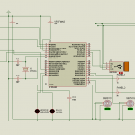
Many of the components of industrial automation systems rely on serial communication to interact with each other and the computers that control them.

They are designed with serial ports to facilitate their use in these automation systems. Serial applications are used to control the devices and their ability to communicate is vital to the operations of countless production lines around the world.

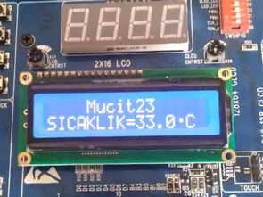
Embedded systems make use of serial communication in a number of ways

Some of the ways that embedded systems use serial communication are:

  • Allowing different parts of a device to communicate with each other;
  • Staying current by downloading firmware updates;
  • Providing users a testing or debugging interface;
  • Communicating with external devices.

Developers and software engineers who are tasked with implementing serial communication in embedded devices must rely on their knowledge of the protocols that form the backbone of this data transmission method.

There are many serial protocols in use, but the RS232/RS422/RS485 standards are the ones most commonly used.

You will find these protocols used extensively in industrial automation and embedded systems which make use of serial communication.

Through the use of devices like USB to serial converters, computers that do not possess a serial port can still communicate with serial devices.

There are several advantages that serial communication offers over alternative technologies such as Ethernet, USB or WiFi. While these other options may provide higher connection speed, they are not as easy to implement as serial technology.

The majority of operating systems include built-in support for serial ports and the interfaces do not need to have custom drivers installed.

The absence of serial ports on the current generation of laptops can be an impediment to developers who need to interact with serial devices and applications.

It definitely hinders their development efforts and makes it difficult to test and troubleshoot their products. But there are hardware and software solutions that can help get around the port limitations of any Windows computer.

There are simple hardware devices that can be used to translate between USB and serial signals. These devices are easy to use and involve connecting one end of the converter to the USB interface on your laptop.

The other end of the converter is a serial interface which can be used to connect to a serial peripheral device. That device can now operate with your laptop in the same way as if it was equipped with serial ports.

A more effective solution to the lack of serial interfaces is to employ software that can create virtual serial ports which behave as if they were actual physical interfaces.

This eliminates the need for additional hardware and its associated cabling.

Here are two versions of a software tool that provide the user with the ability to create virtual serial ports. Serial hardware and software developers and testers will find these tools to be indispensable.

The same can be said for users working with embedded devices employing serial communication.

Virtual Serial Ports make it possible for computers that do not have any physical serial ports to interact with serial devices.

Virtual COM ports work by sending and receiving data over a network instead of through a cabled connection with the peripheral equipment.

This is accomplished by configuring the computer using specialized software. An excellent choice for creating virtual ports is Virtual Serial Port Driver (VSPD) from Eltima Software.


This communication software facilitates the creation of an unlimited number of virtual serial ports. The virtual ports can be connected via a virtual null-modem cable. Every virtual interface that you create totally emulates the functionality of a physical port.

VSPD makes it easy to create and manage your virtual ports and extend the utility of your serial devices. Using the software allows any machine to access network-connected serial devices despite the lack of physical interfaces.

Now you can take full advantage of serial devices even if you are located on the other side of the world from them.

VSPD is available in Standard and Pro versions and you can test drive both products with a 14-day trial.

The post Implementing serial communication in embedded systems appeared first on PIC Microcontroller.


Interfacing Joystick with PIC Microcontroller

$
0
0

Input devices play a vital role in any electronics projects. These input device help the user to interact with the digital world. An input device can be as simple as a push button or as complicated as a touch screen; it varies based on the requirement of the project. In this tutorial we are going to learn how to interface a joystick with our PIC microcontroller, a joystick is a cool way to interact with the digital world and almost everyone would have used one for playing video games in their adolescence age.

Interfacing-Joystick-with-PIC-Micro-controller

A joystick might seem to be a sophisticated device, but it actually is just a combination of two Potentiometers and a push button. Hence it is also very easy to interface with any MCU provided we know how to use the ADC feature of that MCU. Hence it is would be just a work around for interfacing the Joystick.

Material Required

  • PicKit 3 for programming
  • Joy Stick module
  • PIC16F877A IC
  • 40 – Pin IC holder
  • Perf board
  • 20 MHz Crystal OSC
  • Bergstik pins
  • 220ohm Resistor
  • 5-LEDs of any colour
  • 1 Soldering kit
  • IC 7805
  • 12V Adapter
  • Connecting wires
  • Breadboard

Understanding the Joystick Module:

Joysticks are available in different shapes and sizes. A typical Joystick module is shown in the figure below. A Joystick is nothing more than a couple of potentiometers and push button mounted over a smart mechanical arrangement. The potentiometer is used to keep track of the X and Y movement of the joystick and the button is used to sense if the joystick is pressed. Both the Potentiometers output an analog voltage which depends on the position of the joystick. And we can get the direction of movement by interpreting these voltage changes using some microcontroller.

Understanding the Joystick Module using Pic-microcontroller

Before interfacing any sensor or module with a microcontroller it is important to know how it functions. Here our joystick has 5 output pins out of which two is for power and three is for data. The module should be powered with +5V. The data pins are named as VRX, VRY and SW.

The term “VRX” stands for Variable voltage on X-axis and the term “VRY” stands for Variable voltage in Y-axis and “SW” stands for switch.

So when we move the joystick to left or right the voltage value on VRX will vary and when we vary it up or down VRY will vary. Similarly when we move it diagonally we both VRX and VRY will vary. When we press the switch the SW pin will be connected to ground. The below figure will help you to understand the Output values much better

Axis-value-of-Joystick-Module using Pic-microcontroller

Circuit Diagram:

Now that we know how the Joy stick works, we can arrive at a conclusion that we will need two ADC pins and one digital input pin to read all the three data pins of the Joystick module. The complete circuit diagram is shown in the picture below

Interfacing-circuit-diagram-of-Joystick-with-PIC-Micro-controller

As you can see in circuit diagram, instead of the joystick we have used two potentiometer RV1 and RV3 as analog voltage inputs and a logic input for the switch. You could follow the labels written in violet colour to match the pins names and make your connections accordingly.

Note that the Analog pins are connected to channels A0 and A1 and the digital switch is connected to RB0. We will also have 5 LED lights connected as output, so that we can glow one based on the direction the joystick is moved. So these output pins are connected to PORT C from RC0 to RC4. Once we have panned our circuit diagram we can proceed with the programming, then simulate the program on this circuit then build the circuit on a breadboard and then upload the program to the hardware. To give you an idea my hardware after making the above connections is shown below

Interfacing-circuit-hardware-of-Joystick-using-PIC-Micro-controller

Programming for Interfacing the Joystick:

The program to interface joystick with PIC is simple and straight forward. We already know that which pins the Joystick is connected to and what their function is, so we simply have to read the analog voltage from the pins and control the output LED’s accordingly.

The complete program to do this is given at the end of this document, but for explaining things I am breaking the code in to small meaningful snippets below.

As always the program is started by setting the configuration bits, we are not going to discuss much about setting configurations bits because we have already learnt it in the LED Blinking project and it is the same for this project also. Once the configurations bits are set we have to define the ADC functions for using the ADC module in our PIC. These function were also learnt in the how to use ADC with PIC tutorial. After that, we have to declare which pins are inputs and which are output pins. Here the LED is connected to PORTC so they are output pins and the Switch pin of Joystick is a digital input pin. So we use the following lines to declare the same:

//*****I/O Configuration****//
TRISC=0X00; //PORT C is used as output ports
PORTC=0X00; //MAke all pins low
TRISB0=1; //RB0 is used as input
//***End of I/O configuration**///

The ADC pins need not be defined as input pins because they when using the ADC function it will be assigned as input pin. Once the pins are defined, we can call the ADC_initialize function which we defined earlier. This function will set the required ADC registers and prepare the ADC module.

ADC_Initialize(); //Configure the ADC module

Now, we step into our infinite while loop. Inside this loop we have to monitor the values of VRX, VRY and SW and based on the values we have to control the led’s output.  We can begin the monitoring process by reading the analog voltage of VRX and VRY by using the below lines

    int joy_X = (ADC_Read(0)); //Read the X-Axis of joystick
    int joy_Y = (ADC_Read(1)); //Read the Y-Axis of Joystick

This line will save the value of VRX and VRY in the variable joy_X and joy_Y respectively. The function ADC_Read(0)means we are reading the ADC value from channel 0 which is pin A0. We have connected VRX and VRY to pin A0 and A1 and so we read from 0 and 1.

If you can recollect from our ADC tutorial we know that we read the Analog Voltage the PIC being a digital device will read it from 0 to 1023. This value depends on the position of the joystick module. You can use the label diagram above to know what value you can expect for every position of the joystick.

Here I have used the limit value of 200 as lower limit and a value of 800 as upper limit. You can use anything you want. So let’s use these values and start glowing the LED s accordingly. To do this we have to compare the value of joy_X with the pre-defined values using an IF loop and make the LED pins high or low as shown below. The comment lines will help you to understand better

    if (joy_X < 200) //Joy moved up
    {RC0=0; RC1=1;} //Glow upper LED
    else if (joy_X > 800) //Joy moved down
    {RC0=1; RC1=0;} //Glow Lower LED
    else //If not moved
    {RC0=0; RC1=0;} //Turn off both led

We can similarly do the same for the value of Y-axis as well. We just have to replace the variable joy_X with joy_Y and also control the next two LED pins as shown below. Note that when the joystick is not moved we turn off both the LED lights.

    if (joy_Y < 200) //Joy moved Left
    {RC2=0; RC3=1;} //Glow left LED
    else if (joy_Y > 800) //Joy moved Right
    {RC2=1; RC3=0;} //Glow Right LED
    else //If not moved
    {RC2=0; RC3=0;} //Turn off both LED

Now we have one more final thing to do, we have to check the switch if is pressed. The switch pin is connected to RB0 so we can again use if loop and check if it is on. If it is pressed we will turn of the LED to indicate that the switch has been pressed.

    if (RB0==1) //If Joy is pressed
        RC4=1; //Glow middle LED
    else
        RC4=0; //OFF middle LED

Simulation View:

The complete project can be simulated using the Proteus software. Once you have written the program compile the code and link the hex code of the simulation to the circuit. Then you should notice the LED lights glowing according to the position of the potentiometers. The simulation is shown below:

Simulation-of-Interfacing-Joystick-with-PIC-Micro-controller

Hardware and Working:

After verifying the code using the Simulation, we can build the circuit on a bread board. If you have been following the PIC tutorials you would have noticed that we use the same perf board which has the PIC and 7805 circuit soldered to it.  If you are also interested in making one so that you use it with all your PIC projects then solder the circuit on a perf board.  Or you can also build the complete circuit on a breadboard also. Once the hardware is done it would be something like this below.

Hardware and Working using Pic-microcontroller

Now upload the code to the PIC microcontroller using the PICkit3. You can refer the LED Blink project for guidance. You should notice the yellow light go high as soon as the program is uploaded. Now use the joystick and vary the knob, for each direction of the joystick you will notice the respective LED going high. When the switch in the middle is pressed, it will turn off the LED in the middle.

This working is just an example, you can build a lot of interesting projects on top it. The complete working of the project can also be found at the video given at the end of this page.

Hope you understood the project and enjoyed building it, if you have any problem in doing so feel free to post it on the comment section below or write it on the forums for getting help.

Code

/*
* File:   PIC_Joystick.c
* Author: Aswinth
* This program can read the values from a joy stick and control the LED based on the values
* Created on 3 May, 2018, 4:05 PM for www.circuitdigest.com
*/

// CONFIG
#pragma config FOSC = HS        // Oscillator Selection bits (HS oscillator)
#pragma config WDTE = OFF       // Watchdog Timer Enable bit (WDT disabled)
#pragma config PWRTE = ON       // Power-up Timer Enable bit (PWRT enabled)
#pragma config BOREN = ON       // Brown-out Reset Enable bit (BOR enabled)
#pragma config LVP = OFF        // Low-Voltage (Single-Supply) In-Circuit Serial Programming Enable bit (RB3 is digital I/O, HV on MCLR must be used for programming)
#pragma config CPD = OFF        // Data EEPROM Memory Code Protection bit (Data EEPROM code protection off)
#pragma config WRT = OFF        // Flash Program Memory Write Enable bits (Write protection off; all program memory may be written to by EECON control)
#pragma config CP = OFF         // Flash Program Memory Code Protection bit (Code protection off)

// #pragma config statements should precede project file includes.
// Use project enums instead of #define for ON and OFF.

#include <xc.h>
#define _XTAL_FREQ 20000000

void ADC_Initialize()
{
ADCON0 = 0b01000001; //ADC ON and Fosc/16 is selected
ADCON1 = 0b11000000; // Internal reference voltage is selected
}

unsigned int ADC_Read(unsigned char channel)
{
ADCON0 &= 0x11000101; //Clearing the Channel Selection Bits
ADCON0 |= channel<<3; //Setting the required Bits
__delay_ms(2); //Acquisition time to charge hold capacitor
GO_nDONE = 1; //Initializes A/D Conversion
while(GO_nDONE); //Wait for A/D Conversion to complete
return ((ADRESH<<8)+ADRESL); //Returns Result
}

void main()
{

//*****I/O Configuration****//
TRISC=0X00; //PORT C is used as output ports
PORTC=0X00; //MAke all pins low
TRISB0=1; //RB0 is used as input
//***End of I/O configuration**///

ADC_Initialize(); //Configure the ADC module

while(1)
{

int joy_X = (ADC_Read(0)); //Read the X-Axis of joystick
int joy_Y = (ADC_Read(1)); //Read the Y-Axis of Joystick

if (joy_X < 200) //Joy moved up
{RC0=0; RC1=1;} //Glow upper LED
else if (joy_X > 800) //Joy moved down
{RC0=1; RC1=0;} //Glow Lower LED
else //If not moved
{RC0=0; RC1=0;} //Turn off both led

if (joy_Y < 200) //Joy moved Left
{RC2=0; RC3=1;} //Glow left LED
else if (joy_Y > 800) //Joy moved Right
{RC2=1; RC3=0;} //Glow Right LED
else //If not moved
{RC2=0; RC3=0;} //Turn off both LED

if (RB0==1) //If Joy is pressed
RC4=1; //Glow middle LED
else
RC4=0; //OFF middle LED

}

}

The post Interfacing Joystick with PIC Microcontroller appeared first on PIC Microcontroller.

Interfacing PIR Sensor with PIC Microcontroller

$
0
0

Today we are simple going to interface PIR with PIC Microcontroller PIC16F877A. In this circuit if some moving objects comes in the range of PIR sensor, the buzzer will start beeping.

Interfacing-PIR-Sensor-with-PIC-Microcontroller

Material Required

  • PicKit 3
  • PIR Sensor.
  • PIC16F877A IC
  • 40 – Pin IC holder
  • Perf board
  • 20 MHz Crystal OSC
  • Female and Male Bergstick pins
  • 33pf Capacitor – 2Nos, 100uf and 10uf cap.
  • 680 ohm, 10K and 560ohm Resistor
  • LED of any color
  • 1 Soldering kit
  • IC 7805
  • 12V Adapter
  • Buzzer
  • Connecting wires
  • Breadboard

PIR Sensor:

PIR sensor is inexpensive, low-power and easy to use Motion Detections Sesnor. PIR sensor only receives infrared rays, not emits that’s why it’s called passive. PIR sense any change in heat, and if there is a change it gives HIGH at OUTPUT. PIR Sensor also referred as Pyroelectric or IR motion sensor.

PIR Sensor using Pic-microcontroller

Every object emits some amount of infrared when heated, similar to that human body emits IR due to body heat. Infrared created by every object because of the friction between air and object. The main component of PIR sensor is Pyroelectric sensor. Along with this, BISS0001 (“Micro Power PIR Motion Detector IC”), some resistors, capacitors and other components used to build PIR sensor. BISS0001 IC take the input from sensor and does processing to make the output pin HIGH or LOW accordingly.

You can also adjust distance sensitivity and time duration for which the output pin will be high once motion is detected. It has two potentiometer knobs to adjust these two parameters.

Circuit Diagram

Circuit Diagram using Pic-mirocontroller

PIC Microcontroller:

In order to program the PIC microcontroller for interfacing PIR, we will need an IDE (Integrated Development Environment), where the programming takes place. A compiler, where our program gets converted into MCU readable form called HEX files. An IPE (Integrated Programming Environment), which is used to dump our hex file into our PIC MCUs.

IDE: MPLABX v3.35

IPE: MPLAB IPE v3.35

Compiler: XC8

Microchip has given all these three software for free. They can be downloaded directly from their official page. I have also provided the link for your convenience. Once downloaded install them on your computer. If you have any problem doing so you can view the Video given at the end.

To dump or upload our code into PIC, we will need PICkit 3. The PICkit 3 programmer/debugger is a simple, low-cost in-circuit debugger that is controlled by a PC running MPLAB IDE (v8.20 or greater) software on a Windows platform. The PICkit 3 programmer/debugger is an integral part of the development engineer’s tool suite. In addition to this we will also need other hardware like Perf board, Soldering station, PIC ICs, Crystal oscillators, capacitors etc. But we will add them to our list as we progress through our tutorials.

We will be programming our PIC16F877A using the ICSP option that is available in our MCU.

To burn the code, follow below steps:

  1. Launch the MPLAB IPE.
  2. Connect one end of your PicKit 3 to your PC and other end to your ICSP pins on perf board.
  3. Connect to your PIC device by clicking on the connect button.
  4. Browse for the Blink HEX file and click on Program.

Code and Explanation

First, we need to set the configuration bits in the pic microcontroller and then start with void main function.

In the below code, ‘XC.h’ is the header file that contain all the friendly names for the pins and peripherals. Also we have defined crystal oscillator frequency, PIR and Buzzer pins connection in below code.

#include <xc.h>
#define _XTAL_FREQ 20000000 //Specify the XTAL crystall FREQ
#define PIR RC0
#define Buzzer RB2

In the void main (), ‘TRISB=0X00’ is used to instruct the MCU that the PORTB pins are used as OUTPUT, ‘TRISC=0Xff’ is used to instruct the MCU that the PORTB pins are used as INPUT. And ‘PORTB=0X00’ is used to instruct the MCU to make all the OUTPUT of RB3 Low.

TRISB=0X00;
TRISC=0Xff;
PORTB=0X00; //Make all output of RB3 LOW

As per the below code, whenever PIR get HIGH the buzzer will get HIGH or else it remain OFF.

while(1) //Get into the Infinie While loop
{
    if(PIR ==1){
        Buzzer=1;
       __delay_ms(1000);   //Wait
    }
    else{
        Buzzer=0;
    }
  }
}

Complete Code with a Demo Video is given at the end of this project.

Working of PIR Sensor with PIC Microcontroller:

This project does not have any complicated hardware setup, we are again using the same PIC Microcontroller board(as shown below) which we have created in LED blinking Tutorial. Simply connect the PIR Sensor Module with your PIC Microcontroller board according to the connection diagram. Once you are done with the connections, simply dump the code using your PicKit 3 programmer as explained in previous tutorial and enjoy your output.

LED-blinking-using-PIC-microcontroller

After uploading the program, PIR sensor is ready to give OUTPUT. Whenever, a human being or object that emits IR comes in the range of PIR it gives HIGH to the OUTPUT. And, based on that output the buzzer will operate. If PIR output is high buzzer input gets high and vice versa.

Working of PIR Sensor using PIC Microcontroller

You can control the distance of sensing and time delay by using two potentiometers fixed on the PIR module.

Code:

// ‘C’ source line config statements

// CONFIG
#pragma config FOSC = HS        // Oscillator Selection bits (HS oscillator)
#pragma config WDTE = OFF       // Watchdog Timer Enable bit (WDT disabled)
#pragma config PWRTE = OFF      // Power-up Timer Enable bit (PWRT disabled)
#pragma config BOREN = ON       // Brown-out Reset Enable bit (BOR enabled)
#pragma config LVP = OFF        // Low-Voltage (Single-Supply) In-Circuit Serial Programming Enable bit (RB3 is digital I/O, HV on MCLR must be used for programming)
#pragma config CPD = OFF        // Data EEPROM Memory Code Protection bit (Data EEPROM code protection off)
#pragma config WRT = OFF        // Flash Program Memory Write Enable bits (Write protection off; all program memory may be written to by EECON control)
#pragma config CP = OFF         // Flash Program Memory Code Protection bit (Code protection off)

// #pragma config statements should precede project file includes.
// Use project enums instead of #define for ON and OFF.

#include <xc.h>

#define _XTAL_FREQ 20000000 //Specify the XTAL crystall FREQ
#define PIR RC0
#define Buzzer RB2

void main() //The main function
{
TRISB=0X00; //Instruct the MCU that the PORTB pins are used as Output.
TRISC=0Xff; //Instruct the MCU that the PORTB pins are used as Input.
PORTB=0X00; //Make all output of RB3 LOW

while(1) //Get into the Infinie While loop
{
if(PIR ==1){
Buzzer=1;
__delay_ms(1000);   //Wait
}
else{
Buzzer=0;
}
}

}

Video:

Read more detail:Interfacing PIR Sensor with PIC Microcontroller

The post Interfacing PIR Sensor with PIC Microcontroller appeared first on PIC Microcontroller.

Interfacing GPS Module with PIC Microcontroller

$
0
0

GPS is the short-form of Global Positioning System. It is a system which provide accurate Altitude, Latitude, Longitude, UTC time and many more information, which are taken from 2, 3, 4 or more satellite. To read data from GPS, we need some Microcontroller and we already interfaced GPS with Arduino and with Raspberry Pi.

Interfacing-GPS-Module-using-PIC-Microcontroller

We have selected G7020 GPS module which is made by U-blox. We will receive Longitude and latitude of a particular position from satellite and will display the same on a 16×2 Character LCD. So here we will interface GPS with PIC16F877A microcontroller by microchip.

Components Required:

  1. Pic16F877A – PDIP40 package
  2. Bread Board
  3. Pickit-3
  4. 5V adapter
  5. LCD JHD162A
  6. uBLOX-G7020 GPS module
  7. Wires to connect peripherals.
  8. 4.7k Resistors
  9. 10k pot
  10. 20mHz Crystal
  11. 2 pcs 33pF ceramic capacitors

Circuit Diagram and Explanation:-

Interfacing-Circuit-Diagram-for-GPS-Module-using-PIC-Microcontroller


16×2 character LCD is connected across PIC16F877A microcontroller, in which RB0, RB1, RB2 is connected respectively to the LCD pin which is RS, R/W , and E. RB4, RB5, RB6 and RB7 are connected across LCD’s 4 pin D4, D5, D6, D7. The LCD is connected in 4bit mode or nibble mode.

A crystal Oscillator of 20MHz with two ceramic capacitor of 33pF connected across OSC1 and OSC2 pin. It will provide constant 20 MHz clock frequency to the microcontroller.

uBlox-G7020 GPS module, receive and transmit data using UART. PIC16F877A consists one USART driver inside the chip, we will receive data from GPS module by USART, so a cross connection will be made from the microcontroller Rx pin to GPS’s Tx pin and USART Receive pin connected across GPS’s Transmit pin.

The uBlox-G7020 has color code for the pins. The Positive or 5V pin is in Red color, the Negative or GND pin is in Black color and the Transmit pin is in Blue color.

I have connected all this in the breadboard.

Getting Location Data from GPS:

Let’s see how to interface GPS using USART and see the result in a 16×2 character LCD.

The Module will transmit data in multiple strings at 9600 Baud Rate. If we use an UART terminal with 9600 Baud rate, we will see the data received by GPS.

GPS module sends the Real time tracking position data in NMEA format (see the screenshot above). NMEA format consist several sentences, in which four important sentences are given below. More detail about the NMEA sentenceand its data format can be found here.

  • $GPGGA: Global Positioning System Fix Data
  • $GPGSV: GPS satellites in view
  • $GPGSA: GPS DOP and active satellites
  • $GPRMC: Recommended minimum specific GPS/Transit data

This is the data received by GPS when connected on 9600 baud rate.

$GPRMC,141848.00,A,2237.63306,N,08820.86316,E,0.553,,100418,,,A*73
$GPVTG,,T,,M,0.553,N,1.024,K,A*27
$GPGGA,141848.00,2237.63306,N,08820.86316,E,1,03,2.56,1.9,M,-54.2,M,,*74
$GPGSA,A,2,06,02,05,,,,,,,,,,2.75,2.56,1.00*02
$GPGSV,1,1,04,02,59,316,30,05,43,188,25,06,44,022,23,25,03,324,*76
$GPGLL,2237.63306,N,08820.86316,E,141848.00,A,A*65

When we use GPS module for tracking any location, we only need coordinates and we can find this in $GPGGA string. Only $GPGGA (Global Positioning System Fix Data) String is mostly used in programs and other strings are ignored.

$GPGGA,141848.00,2237.63306,N,08820.86316,E,1,03,2.56,1.9,M,-54.2,M,,*74

What is the meaning of that line?

Meaning of that line is:-

1. String always starts with a “$” sign

2. GPGGA stands for Global Positioning System Fix Data

3. “,” Comma indicates the separation between two values

4. 141848.00: GMT time as 14(hr):18(min):48(sec):00(ms)

5. 2237.63306,N: Latitude 22(degree) 37(minutes) 63306(sec) North

6. 08820.86316,E: Longitude 088(degree) 20(minutes) 86316(sec) East

7. 1 : Fix Quantity 0= invalid data, 1= valid data, 2=DGPS fix

8. 03 :  Number of satellites currently viewed.

9. 1.0: HDOP

10. 2.56,M : Altitude (Height above sea level in meter)

11. 1.9,M : Geoids height

12. *74 : checksum

So we need No. 5 and No.6 to gather information about the module location or, where it is located.

Steps to Interface GPS with PIC Microcontroller:-

  1. Set the configurations of the microcontroller which include Oscillator configuration.
  2. Set the Desired port for LCD including TRIS register.
  3. Connect the GPS module to the microcontroller using USART.
  4. Initialize the system USART in continuous receive mode, with 9600 baud rate and LCD with 4bit mode.
  5. Take two character arrays depending on the Length of Latitude and Longitude.
  6. Receive one character bit at a time and check whether it is started from $ or not.
  7. If $ Receive then it is a string, we need to check GPGGA, this 5 letters and the comma.
  8. If it is GPGGA, then we will skip the time, and look for the Latitude and Longitude, We will store the Latitude and Longitude in two character array until N (North) and E (East) not received.
  9. We will print the array in LCD.
  10. Clear the array.

Steps to Interface GPS using PIC Microcontroller

Code Explanation:

Let’s look at the code line by line. The first few lines are for setting up configuration bits which were explained in the previous tutorial so I am skipping them for now. The complete Code is given at the end of this tutorial.

These five lines are used for including library header files, lcd.h and eusart.h is for LCD and USART respectively. And xc.h is for microcontroller header file.

#include <xc.h>
#include <stdio.h>
#include <string.h>
#include "supporing_cfile\lcd.h"
#include "supporing_cfile\eusart1.h"

In void main() function, the system_init(); function is used to initialize LCD and USART.

Void main(void) {
    TRISB = 0x00; // Setting as output
    system_init();

The lcd_init(); and EUSART_Intialize(); is called from the two libraries lcd.h and eusart.h

void system_init(void){
    lcd_init(); // This will initialise the lcd
    EUSART1_Initialize(); // This will initialise the Eusart
}

In while loop we break the GPGGA string to get the Longitude and Latitude coordinate. We receiving one bit at a time and compare it with individual characters present in GPGGA string.

We break the codes we will get:-

        incomer_data=EUSART1_Read(); // Check the string '$GPGGA,'
/*------------------------------ Step by step finding the GPGGA line----------------------------*/
        if(incomer_data=='$'){ // First statement of the GPS data start with a $ sign
            incomer_data=EUSART1_Read(); // If the first if become true then the next phase
            if(incomer_data=='G'){
                incomer_data=EUSART1_Read();
                if(incomer_data=='P');{
                    incomer_data=EUSART1_Read();
                    if(incomer_data=='G');{
                    incomer_data=EUSART1_Read();
                    if(incomer_data=='G'){
                        incomer_data=EUSART1_Read();
                        if(incomer_data=='A'){
                            incomer_data=EUSART1_Read();
                            if(incomer_data==','){ // first , received
                                incomer_data=EUSART1_Read(); // At this stage Final check in done, GPGGA is found.

By using this code we skipping the UTC time.

while (incomer_data != ','){ // skipping GMT Time 
                                    incomer_data=EUSART1_Read();
                                }

This code is for storing the Latitude and Longitude data in the character array.

                       incomer_data=EUSART1_Read();
                                latitude[0] = incomer_data;                                

                                while(incomer_data != ','){
                                for(array_count=1;incomer_data!='N';array_count++){
                                    incomer_data=EUSART1_Read();
                                    latitude[array_count]=incomer_data; // Store the Latitude data
                                    }
                                    incomer_data=EUSART1_Read();

                                    if(incomer_data==','){
                                        for(array_count=0;incomer_data!='E';array_count++){
                                        incomer_data=EUSART1_Read();
                                        longitude[array_count]=incomer_data; // Store the Longitude data
                                        }
                                    }

And finally we have printed longitude and latitude on LCD.

                        array_count=0;                                    
                                    lcd_com(0x80); // LCD line one selection
                                    while(array_count<12){ // Array of Latitude data is 11 digit
                                        lcd_data(latitude[array_count]); // Print the Latitude data
                                        array_count++;
                                        }
                           array_count=0;
                                    lcd_com(0xC0); // Lcd line two selection
                                    while(array_count<13){ // Array of Longitude data is 12 digit
                                        lcd_data(longitude[array_count]); // Print the Longitude data
                                        array_count++;
                                    }                   

This is how we can interface GPS module with PIC Microcontroller to get the Latitude and longitude of current location.

Complete code and header files are given below.

Code

/*
* File:   main.c
* Author: Sourav Gupta
* By:- circuitdigest.com
* Created on April 1, 2018, 2:26 PM
*/

// PIC16F877A Configuration Bit Settings

// ‘C’ source line config statements

// CONFIG
#pragma config FOSC = HS        // Oscillator Selection bits (HS oscillator)
#pragma config WDTE = OFF       // Watchdog Timer Enable bit (WDT disabled)
#pragma config PWRTE = OFF      // Power-up Timer Enable bit (PWRT disabled)
#pragma config BOREN = ON       // Brown-out Reset Enable bit (BOR enabled)
#pragma config LVP = OFF         // Low-Voltage (Single-Supply) In-Circuit Serial Programming Enable bit (RB3/PGM pin has PGM function; low-voltage programming enabled)
#pragma config CPD = OFF        // Data EEPROM Memory Code Protection bit (Data EEPROM code protection off)
#pragma config WRT = OFF        // Flash Program Memory Write Enable bits (Write protection off; all program memory may be written to by EECON control)
#pragma config CP = OFF         // Flash Program Memory Code Protection bit (Code protection off)


#include <xc.h>
#include <stdio.h>
#include <string.h>
#include “supporing_cfile\lcd.h”
#include “supporing_cfile\eusart1.h”

/*
Hardware related definition
*/
#define _XTAL_FREQ 200000000 //Crystal Frequency, used in delay

/*
Other Specific definition
*/
void system_init(void);

unsigned char incomer_data = 0;
unsigned char longitude[13];
unsigned char latitude[13];
unsigned int array_count=0;

/* Sample line received from the GPS :-

[$GPGGA,100156.000,2690.9416,N,07547.8441,E,1,08,1.0,442.8,M,-42.5,M,,0000*71]

1. string always starts with a ?$? sign
2. GPGGA : Global Positioning System Fix Data
3. ?,? Comma indicates the separation between two values
4. 100156.000 : GMT time as 10(hr):01(min):56(sec):000(ms)
5. 2650.9416,N: Latitude 26(degree) 50(minutes) 9416(sec) North
6. 07547.8441,E: Longitude 075(degree) 47(minutes) 8441(sec) East
7. 1 : Fix Quantity 0= invalid data, 1= valid data, 2=DGPS fix
8. 08 :  Number of satellites currently viewed.
9. 1.0: HDOP
10. 442.8,M : Altitude (Height above sea level in meter)
11. -42.5,M : Geoids height
12. __ , DGPS data
13. 0000 : DGPS data
14. *71 : checksum
*/

void main(void) {
TRISB = 0x00; // Setting as output
system_init(); // System getting ready and initialising the LCD and USART driver.
//LCD_ScrollMessage(“Circuitdigest.com”);
while(1){
incomer_data=EUSART1_Read(); // Check the string ‘$GPGGA,’
/*—————————— Step by step finding the GPGGA line—————————-*/
if(incomer_data==’$’){ // First statement of the GPS data start with a $ sign
incomer_data=EUSART1_Read(); // If the first if become true then the next phase
if(incomer_data==’G’){
incomer_data=EUSART1_Read();
if(incomer_data==’P’);{
incomer_data=EUSART1_Read();
if(incomer_data==’G’);{
incomer_data=EUSART1_Read();
if(incomer_data==’G’){
incomer_data=EUSART1_Read();
if(incomer_data==’A’){
incomer_data=EUSART1_Read();
if(incomer_data==’,’){ // first , received
incomer_data=EUSART1_Read(); // At this stage Final check in done, GPGGA is found.
while (incomer_data != ‘,’){ // skipping GMT Time
incomer_data=EUSART1_Read();
}
incomer_data=EUSART1_Read();
latitude[0] = incomer_data;
while(incomer_data != ‘,’){
for(array_count=1;incomer_data!=’N’;array_count++){
incomer_data=EUSART1_Read();
latitude[array_count]=incomer_data; // Store the Latitude data
}

incomer_data=EUSART1_Read();
if(incomer_data==’,’){
for(array_count=0;incomer_data!=’E’;array_count++){
incomer_data=EUSART1_Read();
longitude[array_count]=incomer_data; // Store the Longitude data
}
}
array_count=0;
//lcd_com(0x80); // LCD line one selection
while(array_count<12){ // Array of Latitude data is 11 digit
lcd_data(latitude[array_count]); // Print the Latitude data
array_count++;
}
array_count=0;
lcd_com(0xC0); // Lcd line two selection
while(array_count<13){ // Array of Longitude data is 12 digit
lcd_data(longitude[array_count]); // Print the Longitude data
array_count++;
}
//lcd_com(0x01); //clear LCD
}
}
}

}
}
}
}
}
for(array_count=0;array_count<=13;array_count++){
incomer_data=0;
latitude[array_count]=0;
longitude[array_count]=0;

}
array_count = 0;
}
}

/*
This Function is for system initialisations.
*/

void system_init(void){
lcd_init(); // This will initialise the lcd
EUSART1_Initialize(); // This will initialise the Eusart
}

The post Interfacing GPS Module with PIC Microcontroller appeared first on PIC Microcontroller.

Interfacing Ultrasonic Sensor HC-SR04 with PIC Microcontroller

$
0
0

For any project to come alive, we need to use sensors. Sensors acts as the eyes and ears for all embedded application, it helps the digital Microcontroller to understand what is actually happening in this real Analog world. In this tutorial we will be learning how to Interface Ultrasonic Sensor HC-SR04 with PIC microcontroller.

Interfacing Ultrasonic Sensor HC-SR04 using PIC Microcontroller

The HC-SR04 is an ultrasonic sensor which can be used to measure distance anywhere between 2cm to 450cm (theoretically). This sensor has proved itself worthy by fitting into many projects which involves obstacles detection, distance measuring, environment mapping etc. At the end of this article you will learn how this sensor works and how to interface it with PIC16F877A microcontroller to measure the distance and display it on the LCD screen. Sounds interesting right!! So let’s get started…

Materials Required:

  1. PIC16F877A MCU with programming set-up
  2. LCD 16*2 display
  3. Ultrasonic sensor (HC-SR04)
  4. Connecting wires

How does an Ultrasonic Sensor work?

Before we get any further, we should know how an Ultrasonic sensor works so that we can understand this tutorial much better. The ultrasonic sensor used in this project is shown below.

Ultrasonic Sensor work using Pic-microcontroller

As you can see it has two circular eyes like projections and four pins coming out of it. The two eye like projections are the Ultrasonic wave (hereafter referred as US wave) Transmitter and receiver. The transmitter emits an US wave at a frequency of 40Hz, this wave travels through the air and gets reflected back when it senses an object. The returning waves are observed by the receiver. Now we know the time taken for this wave to get reflected and come back and the speed of the US wave is also universal (3400cm/s). Using this information and the below high school formulae we can calculate the distance covered.

Distance = Speed × Time

Now that we know how an US sensor works, let us how it can be interfaced with any MCU/CPU using the four pins. These four pins are Vcc, Trigger, Echo and Ground respectively. The module works on +5V and hence the Vcc and ground pin is used to power the module. The other two pins are the I/O pins using which we communicate to our MCU. The trigger pin should be declared as an output pin and made high for a 10uS, this will transmit the US wave into the air as 8 cycle sonic burst. Once the wave is observed the Echo pin will go high for the exact interval of time which was taken by the US wave to return back to the sensor module. Hence this Echo pin will be declared as inputand a timer will be used to measure how long the pin was high. This could further be understood by the timing diagram below.

Ultrasonic-Timing-Diagram using Pic-microcontroller

Circuit Diagram:

The complete circuit diagram for interfacing Ultrasonic Sensor with PIC16F877A is shown below:

ultrasonic-sensor-interfacing Circuit Diagram-using-pic-microcontroller


As shown, the circuit involves nothing more than a LCD display and the Ultrasonic sensor itself. The US sensor can be powered by +5V and hence it is directly powered by the 7805 voltage regulator. The sensor has one output pin (Trigger pin) which is connected to pin 34 (RB1) and the input pin (Echo pin) is connected to pin 35 (RB2). The complete pin connection is illustrated in the table below.

S.No:

PIC Pin Number

Pin Name

Connected to

1

21

RD2

RS of LCD

2

22

RD3

E of LCD

3

27

RD4

D4 of LCD

4

28

RD5

D5 of LCD

5

29

RD6

D6 of LCD

6

30

RD7

D7 of LCD

7

34

RB1

Trigger of US

8

35

RB2

Echo of US

Programming your PIC Microcontroller:

The complete program for this tutorial is given at the end of this page, further below I have explained the code into small meaning full chunks for you to understand. As said earlier the program involves the concept of LCD interfacing and Timer which will not explained in details in this tutorial since we have already covered them in the previous tutorials.

Inside, the main function we start with initializing the IO pins and other registers as usual. We define the IO pins for LCD and US sensor and also initiate the Timer 1 register by setting it to work on 1:4 pre-scalar and to use internal clock (Fosc/4)

  TRISD = 0x00; //PORTD declared as output for interfacing LCD
    TRISB0 = 1;        //Define the RB0 pin as input to use as interrupt pin
    TRISB1 = 0; //Trigger pin of US sensor is sent as output pin
    TRISB2 = 1; //Echo pin of US sensor is set as input pin      
    TRISB3 = 0; //RB3 is output pin for LED
    T1CON=0x20; //4 pres-scalar and internal clock

The Timer 1 is a 16-bit timer used in PIC16F877A, the T1CON register control the parameters of the timer module and the result will be stored in TMR1H and TMR1L since it a 16-bit result the first 8 will be stored in TMR1H and the next 8 in TMR1L. This timer can be turned on or off using TMR1ON=0 and TMR1ON=1 respectively.

Now, the timer is ready to use, but we have to send the US waves out of the sensor, to do this we have to keep the Trigger pin high for 10uS, this is done by the following code.

        Trigger = 1;
        __delay_us(10);          
        Trigger = 0;

As shown in timing diagram above, the Echo pin will stay low till the wave return back and will then go high and stay high for the exact time taken for the waves to return back. This time has to be measured by the Timer 1 module, which can be done by the below line

        while (Echo==0);
            TMR1ON = 1;
        while (Echo==1);
            TMR1ON = 0;

Once the time is measured the resulting value will be saved in the registers TMR1H and TMR1L, these registers have to be clubbed to gather to get the 16-bit value. This is done by using the line below

time_taken = (TMR1L | (TMR1H<<8));

This time_taken will be in form bytes, to get the actual time value we have to use the below formula.

Time = (16-bit register value) * (1/Internal Clock) * (Pre-scale)
Internal Clock = Fosc/4

Where in our case,
Fosc = 20000000Mhz and Pre-scale = 4

Hence the value of Internal Clock will be 5000000Mhz and the value of time will be

Time = (16-bit register value) * (1/5000000) * (4)
          = (16-bit register value) * (4/5000000)
          = (16-bit register value) * 0.0000008 seconds (OR)
Time = (16-bit register value) * 0.8 micro seconds

In our program the value of the 16-bit register is stored in the variable time_taken and hence the below line is used to calculate the time_taken in micro seconds

time_taken = time_taken * 0.8;

Next we have to find how to calculate the distance. As we know distance = speed * time. But here the result should be divided by 2 since the wave is covering both the transmitting distance and receiving distance. The speed of us wave (sound) is 34000cm/s.

Distance = (Speed*Time)/2
                = (34000 * (16-bit register value) * 0.0000008) /2
Distance = (0.0272 * 16-bit register value)/2

So the distance can be calculated in centimeters like below:

distance= (0.0272*time_taken)/2;

After calculating the value of distance and time taken we simply have to display them on the LCD screen.

Measuring distance using PIC and Ultrasonic Sensor:

After making the connections and uploading the code, your experimental set-up should look something like this shown in the below picture.

measuring-distance-using-ultrasonic-sensor-and-pic-microcontroller

Now place an object before the sensor and it should display how far the object is from the sensor. You can also notice the time taken being displayed in micro seconds for the wave to transmit and return back.

You can move the object at your preferred distance and check the value that is displayed on the LCD. I was able to measure distance from 2cm to 350cm with an accuracy of 0.5cm. This is quite a satisfactory result! Hope you enjoyed the tutorial and learnt how to make something on your own. If you have any doubts drop them in the comment section below or use the forums.

Code

/*
Interfacing Ultrasonic sensor with PIC16F877A
* Code by: B.Aswinth Raj
* Dated: 19-07-2017
* More details at: www.CircuitDigest.com
*/

#define _XTAL_FREQ 20000000
#define RS RD2
#define EN RD3
#define D4 RD4
#define D5 RD5
#define D6 RD6
#define D7 RD7
#define Trigger RB1 //34 is Trigger
#define Echo RB2//35 is Echo
#include <xc.h>

#pragma config FOSC = HS        // Oscillator Selection bits (HS oscillator)
#pragma config WDTE = OFF       // Watchdog Timer Enable bit (WDT disabled)
#pragma config PWRTE = ON       // Power-up Timer Enable bit (PWRT enabled)
#pragma config BOREN = ON       // Brown-out Reset Enable bit (BOR enabled)
#pragma config LVP = OFF        // Low-Voltage (Single-Supply) In-Circuit Serial Programming Enable bit (RB3 is digital I/O, HV on MCLR must be used for programming)
#pragma config CPD = OFF        // Data EEPROM Memory Code Protection bit (Data EEPROM code protection off)
#pragma config WRT = OFF        // Flash Program Memory Write Enable bits (Write protection off; all program memory may be written to by EECON control)
#pragma config CP = OFF         // Flash Program Memory Code Protection bit (Code protection off)

//LCD Functions Developed by Circuit Digest.
void Lcd_SetBit(char data_bit) //Based on the Hex value Set the Bits of the Data Lines
{
if(data_bit& 1)
D4 = 1;
else
D4 = 0;

if(data_bit& 2)
D5 = 1;
else
D5 = 0;

if(data_bit& 4)
D6 = 1;
else
D6 = 0;

if(data_bit& 8)
D7 = 1;
else
D7 = 0;
}

void Lcd_Cmd(char a)
{
RS = 0;
Lcd_SetBit(a); //Incoming Hex value
EN  = 1;
__delay_ms(4);
EN  = 0;
}

void Lcd_Clear()
{
Lcd_Cmd(0); //Clear the LCD
Lcd_Cmd(1); //Move the curser to first position
}

void Lcd_Set_Cursor(char a, char b)
{
char temp,z,y;
if(a== 1)
{
temp = 0x80 + b – 1; //80H is used to move the curser
z = temp>>4; //Lower 8-bits
y = temp & 0x0F; //Upper 8-bits
Lcd_Cmd(z); //Set Row
Lcd_Cmd(y); //Set Column
}
else if(a== 2)
{
temp = 0xC0 + b – 1;
z = temp>>4; //Lower 8-bits
y = temp & 0x0F; //Upper 8-bits
Lcd_Cmd(z); //Set Row
Lcd_Cmd(y); //Set Column
}
}

void Lcd_Start()
{
Lcd_SetBit(0x00);
for(int i=1065244; i<=0; i–)  NOP();
Lcd_Cmd(0x03);
__delay_ms(5);
Lcd_Cmd(0x03);
__delay_ms(11);
Lcd_Cmd(0x03);
Lcd_Cmd(0x02); //02H is used for Return home -> Clears the RAM and initializes the LCD
Lcd_Cmd(0x08); //Select Row 1
Lcd_Cmd(0x00); //Clear Row 1 Display
Lcd_Cmd(0x0C); //Select Row 2
Lcd_Cmd(0x00); //Clear Row 2 Display
Lcd_Cmd(0x06);
}

void Lcd_Print_Char(char data)  //Send 8-bits through 4-bit mode
{
char Lower_Nibble,Upper_Nibble;
Lower_Nibble = data&0x0F;
Upper_Nibble = data&0xF0;
RS = 1;             // => RS = 1
Lcd_SetBit(Upper_Nibble>>4);             //Send upper half by shifting by 4
EN = 1;
for(int i=2130483; i<=0; i–)  NOP();
EN = 0;
Lcd_SetBit(Lower_Nibble); //Send Lower half
EN = 1;
for(int i=2130483; i<=0; i–)  NOP();
EN = 0;
}

void Lcd_Print_String(char *a)
{
int i;
for(i=0;a[i]!=’\0′;i++)
Lcd_Print_Char(a[i]);  //Split the string using pointers and call the Char function
}
/*****End of LCD Functions*****/

int time_taken;
int distance;
char t1,t2,t3,t4,t5;
char d1,d2,d3;

int main()
{
TRISD = 0x00; //PORTD declared as output for interfacing LCD
TRISB0 = 1;        //DEfine the RB0 pin as input to use as interrupt pin
TRISB1 = 0; //Trigger pin of US sensor is sent as output pin
TRISB2 = 1; //Echo pin of US sensor is set as input pin
TRISB3 = 0; //RB3 is output pin for LED

T1CON=0x20;

Lcd_Start();

Lcd_Set_Cursor(1,1);
Lcd_Print_String(“Ultrasonic sensor”);
Lcd_Set_Cursor(2,1);
Lcd_Print_String(“with PIC16F877A”);

__delay_ms(2000);
Lcd_Clear();

while(1)
{
TMR1H =0; TMR1L =0; //clear the timer bits

Trigger = 1;
__delay_us(10);
Trigger = 0;

while (Echo==0);
TMR1ON = 1;
while (Echo==1);
TMR1ON = 0;

time_taken = (TMR1L | (TMR1H<<8));
distance= (0.0272*time_taken)/2;

time_taken = time_taken * 0.8;

t1 = (time_taken/1000)%10;
t2 = (time_taken/1000)%10;
t3 = (time_taken/100)%10;
t4 = (time_taken/10)%10;
t5 = (time_taken/1)%10;
d1 = (distance/100)%10;
d2 = (distance/10)%10;
d3 = (distance/1)%10;

Lcd_Set_Cursor(1,1);
Lcd_Print_String(“Time_taken:”);
Lcd_Print_Char(t1+’0′);
Lcd_Print_Char(t2+’0′);
Lcd_Print_Char(t3+’0′);
Lcd_Print_Char(t4+’0′);
Lcd_Print_Char(t5+’0′);

Lcd_Set_Cursor(2,1);
Lcd_Print_String(“distance:”);
Lcd_Print_Char(d1+’0′);
Lcd_Print_Char(d2+’0′);
Lcd_Print_Char(d3+’0′);
}
return 0;
}

The post Interfacing Ultrasonic Sensor HC-SR04 with PIC Microcontroller appeared first on PIC Microcontroller.

USB THERMOMETER CIRCUIT CCS C PIC18F4550

$
0
0

Hi All You Guys. How long have you been working on CCS C. CCS will be able to see my level, so it is no longer something to do after arrival. In this article,… Electronics Projects, USB Thermometer Circuit CCS C PIC18F4550 “microchip projects, microcontroller projects, “

USB THERMOMETER CIRCUIT(1)

Hi All You Guys.

How long have you been working on CCS C. CCS will be able to see my level, so it is no longer something to do after arrival.

In this article, I made a small application on the USB communication pic18f4550. I really wanted to deal with the USB. A little uğraştırsada due to the short time for plenty of sample applications around USB thing figured out. I think there’s a common idea in dealing with USB. Because that I haven’t read about this article or the article. Well, first a couple of application korkutsada the USB after the eye really is different from rs232 communication in terms of convenience.

Now, my application

The system is very simple. Depending on the temperature the temperature sensor DS1820 Sıcaklık Sensorü RA5 pic18f4550, PIN information, and sends it to the computer via the USB port. For now only sends to the computer. I’m a little more for the novice yet C # form and showed the form only in order to show the temperature of the communication with the pic.

USB thermometer proteus isis circuit diagram

USB thermometer proteus isis circuit diagram

Vendor ID and ProductID information in the file is determined usb_driver.h. I did both: 0x1111 hex.

USB THERMOMETER CIRCUIT(2)

USB THERMOMETER CIRCUIT (3)

Source: USB THERMOMETER CIRCUIT CCS C PIC18F4550 all files : usb-thermometer-circuit-ccs-c-pic18f4550.rar

The post USB THERMOMETER CIRCUIT CCS C PIC18F4550 appeared first on PIC Microcontroller.

4 CHANNEL USB FAN CONTROL CIRCUIT PIC18F2550 LM335Z

$
0
0

Fan control circuit on a Board of Directors established the computer control program through Pic18f2550 microcontroller 4 channel can be set independently of the rotation speed of the fans is connected. Temperature sensor is... Electronics Projects, 4 Channel USB Fan Control Circuit PIC18F2550 LM335Z”microchip projects, microcontroller projects, pic18f2550 projects, “

USB FAN CONTROL CIRCUIT

Fan control circuit on a Board of Directors established the computer control program through Pic18f2550microcontroller 4 channel can be set independently of the rotation speed of the fans is connected. Temperature sensor is used as LM335Z. The program’s work for Microsoft. NET framework 3.5 must be installed already the program installation files downloading USB fan control software with Visual Basic Express 2008 installation and source files.

If the Microchip C18 Compiler microcontroller Software Lite with pic18f2550 prepared hex and given C source kdları

Note: the Fan control circuit used in standard pc vaults can be connected to the cpu fans or oğutucu fans (100-250ma)

The Intelligent Fan Controller is designed to control the noise generated by the fans inside your computer. It does this by varying their speed based on temperatures measured inside the case. When it is cool the fans will run slowly and they will only speed up when needed… when your computer is running hot.

Anyone with a noisy computer, especially a Media Centre system in the lounge room, will benefit from this project. After installing this device, my computer is now so quiet that I can hardly tell that it is running – and that is a blessed relief.

The main features are:

Configurable speed control based on temperatures measured inside your computer
Control up to eight fans and measure up to four temperatures
USB interface and Windows software for setup and monitoring
It will run independently without the Windows software (once it has been configured)

USB FAN CONTROL CIRCUIT (1)

source4 CHANNEL USB FAN CONTROL CIRCUIT PIC18F2550 LM335Z alternative link4-channel-usb-fan-control-circuit-pic18f2550-lm335z.rar alternative link2

The post 4 CHANNEL USB FAN CONTROL CIRCUIT PIC18F2550 LM335Z appeared first on PIC Microcontroller.

USB INTERFACE CIRCUIT PIC18F2550 DELPHI

$
0
0

The project is written with delphi program microcontroller used USB interface Pic18f2550 control through a variety of commands on the card may be sent 4 channel button input, 4-channel led output, 2 x 16...Electronics Projects, USB Interface Circuit Pic18f2550 Delphi “microchip projects, microcontroller projects, pic18f2550 projects, “

USB INTERFACE CIRCUIT

The project is written with delphi program microcontroller used USB interface Pic18f2550 control through a variety of commands on the card may be sent 4 channel button input, 4-channel led output, 2 x 16 lcd article submission etc. Pic18f2550, including delphi source code and project files have the proteus isis 7.6

USB INTERFACE CIRCUIT (1)

Source: USB INTERFACE CIRCUIT PIC18F2550 DELPHI alternative usb-interface-pic18f2550-delphi.rar alternative link3

The post USB INTERFACE CIRCUIT PIC18F2550 DELPHI appeared first on PIC Microcontroller.


OPEN SOURCE USB OSCILLOSCOPE PROJECT FT245RL PIC16F690 CPLD

$
0
0

Software and hardware all resources are shared open source USB oscilloscope to implement the project’s source C code (PIC16F690), CPLD Logic files, computer programs belonging to the codes (REALbasic) eagle schematics and PCB drawings… Electronics Projects, Open Source USB Oscilloscope Project FT245RL PIC16F690 CPLD “microchip projects, microcontroller projects, “

OPEN SOURCE USB OSCILLOSCOPE

Software and hardware all resources are shared open source USB oscilloscope to implement the project’s source C code (PIC16F690), CPLD Logic files, computer programs belonging to the codes (REALbasic) eagle schematics and PCB drawings are usb section FT245RL based on the system in general Xilinx XCR3128XL CPLD and PIC16F690 on the printed circuit board is very well designed ..

oscilloscope-USB-Controller-Configuration

usb-osiloskop

Source: OPEN SOURCE USB OSCILLOSCOPE PROJECT  alternative open-source-usb-oscilloscope-project-ft245rl-pic16f690-cpld.rar

The post OPEN SOURCE USB OSCILLOSCOPE PROJECT FT245RL PIC16F690 CPLD appeared first on PIC Microcontroller.

PIC18F2550 USB HID PROJECT CSHARP CCS C

$
0
0

USB Hid project microcontroller used in Pic18f2550 software is a computer program designed with CCS C C sharp (Visual Studio 2010). All source code has been given a simple usb hid example also preparedElectronics Projects, PIC18F2550 USB Hid project Csharp CCS C “microchip projects, microcontroller projects, pic18f2550 projects, “

PIC18F2550 USB HID

USB Hid project microcontroller used in Pic18f2550 software is a computer program designed with CCS C C sharp (Visual Studio 2010). All source code has been given a simple usb hid example also prepared with the circuit simulation and proteus isis UsbLibrary. dll files.

SourcePIC18F2550 USB HID PROJECT alternative link: pic18f2550-usb-hid-project-csharp-ccs-c.RAR

The post PIC18F2550 USB HID PROJECT CSHARP CCS C appeared first on PIC Microcontroller.

PIC18F4550 USB MARQUEE DISPLAY SCROLLING TEXT CIRCUIT LED VISUALBASIC

$
0
0

Marquee displaying the text that is sent over the USB port circuit i. … The program used to send text with visual basic source codes prepared and have built on the 8 × 32… Electronics Projects, PIC18F4550 USB Marquee Display Scrolling Text Circuit LED Visualbasic “microchip projects, microcontroller projects, “

LED VISUALBASIC

Marquee displaying the text that is sent over the USB port circuit i. … The program used to send text with visual basic source codes prepared and have built on the 8 × 32 dot Pic18f4550 circuit matrix LEDs 2 is being prepared with the proton IDE pic software with 74hc154.

MARQUEE LED DISPLAY SCROLLING TEXT LED CIRCUIT

MARQUEE LED DISPLAY SCROLLING TEXT LED CIRCUIT

Source: PIC18F4550 USB MARQUEE DISPLAY SCROLLING TEXT CIRCUIT LED VISUALBASIC Computer controlled Marquee Displaying Circuit files Alternative link: pic18f4550-usb-marquee-displaying-circuit-led-visualbasic

The post PIC18F4550 USB MARQUEE DISPLAY SCROLLING TEXT CIRCUIT LED VISUALBASIC appeared first on PIC Microcontroller.

PIC18F4550 PIC18F2550 USB PROJECT VISUALBASIC CIRCUIT

$
0
0

There are approximately 200 USB control software applications are generally prepared with the Visual Basic used PIC18F2550 microcontrollers, the PIC18F4550 codes written in C language. USB ADCs, etc. USB hidden. circuit has a lot... Electronics Projects, PIC18F4550 PIC18F2550 USB Project VisualBasic Circuit”microchip projects, microcontroller projects, pic18f2550 projects, “

USB PROJECT VISUALBASIC CIRCUIT

There are approximately 200 USB control software applications are generally prepared with the Visual Basic used PIC18F2550 microcontrollers, the PIC18F4550 codes written in C language. USB ADCs, etc. USB hidden. circuit has a lot of programs.

USB PROJECT EXAMPLE SCHEMATIC

USB PROJECT EXAMPLE SCHEMATIC(2)
USB PROJECT EXAMPLE SCHEMATIC(3)
USB PROJECT EXAMPLE SCHEMATIC

USB PROJECT LIST PIC18F4550 PIC18F2550

rr2 usb monitor 155.c usb desc hid modificada 145.doc rr2 usb monitor 399.h USB del PIC18F2550.htmadcdacxs7 403.jpg PIC18F2550 y USB.pdfpic18f2550 y usb 134 picrs232 presentacin1 157 archivos c1a9r8l0os 546

CAD8BITS control de 8 rels por usb 439 Dessamblador detectar usb 201 drivers usb cdc EasyHID Ejemplo USB UC EJERCICIO Nº1 CDC entrenadora usb Escritorio Escritorios esquema 138 firmware pic18f2550 187 libreras 206 motor USB h263 Osciloscopio USB pic usb 136 programa ejemplo 176 Prueba 1 USB HIDprueba 212

SIMULAR PULSOS USB TARGETA BULK USB to Serial usb consola USBProject VB.net MPUSBAPI.dll 18f4550.zip comm usb 998.zip LED RGB USB SERIE.zip picrs232 combobox 427.zip probando 02 200.zip usbproject 175.zip software de control 600 control de 8 rels por usb 439 prueba3 931.zip Conexion USB Visual Basic

ADC HID USB USB easyHID descriptores USB VB.net HID USB Visual C# HID Manual de usuario del PicKit2.pdf PIC18F2550 y USB.pdf Decodificando RC5 con PIC.zip EmulatingRS-232overUSB 121004.pdf bidireccional enviodedatos tp2550 usbcombo.zip LCD USB Main.pdf pic18 usb.zip PicUSB.zip simulacion.zip USB LCD TECLADO 8 BITS.zip 1 USB conexion USB usb CDC Osciloscopio pic

Source: PIC18F4550 PIC18F2550 USB PROJECT VISUALBASIC CIRCUIT alternative link USB Project : http://www.mediafire.com/?f2kuuglco8wn48b

alternative link: https://www.dropbox.com/s/ng4pzx1w2se1s8t/usb-projeleri-visual-basic-microchip-18f2550-18f4550.rar

The post PIC18F4550 PIC18F2550 USB PROJECT VISUALBASIC CIRCUIT appeared first on PIC Microcontroller.

Placing code in a specific Rom/Flash/Program Memory Address of Microchip Pic Microcontroller

$
0
0

Recently i was working with 8-bit pic16f877 microcontroller and i want to place program code at a specific rom(read only memory) location. I was working with xc8 compiler and mplabx ide.  Previously i did this same thing many times while using c18 c compiler. C18 compiler uses #pragma code directives to accomplish this task. But when i started with xc8 compiler and put the same #pragma code directive in my code the compiler starts giving errors. I found that the xc8 didn’t support #pragma code directives. So now i have to locate the xc8 macros for accomplishing this task. I searched the internet but did not found any major help regarding it. Then i decided to read the xc8 compiler datasheet. After lot of reading i found some valuable information and now i want to share it with the microcontroller projects community.

I found three methods to store data at a particular location in program memory of pic microcontroller, when working with xc8 compiler. The three macros/directives that i found were

  • __section()
  • __at()
  • ‘@’ qualifier

The first two methods are little complex and difficult to manage, while the third one the ‘@’ qualifier is easy to manage and use. Before using the ‘@’ qualifier one should first check the program memory banks addresses range of the pic microcontroller that he is using. I am using pic16f877 microcontroller, its program memory address range is from 0x0000 to 0x1FFF. The word size is 14 bits and memory size is 8 KB. 

Placing code in a specific Rom Flash Program Memory Address of Microchip Pic Microcontroller

I want my code to start at program memory location/address 0x200. To do so i placed the ‘@’ qualifier at the end of the main function. See the above main function initialization. At the end of the closing brackets i placed the @ qualifier with the program memory address where i want my code to be placed in flash/rom. In the main function i have two for loop functions, generating a random delay.    

After writing code i compiled it with xc8 compiler in mplabx ide. For verifying that the code is placed at the right address, I started mplabx simulator and opened the program memory window to see the code placement. See the result on the left hand side. The code starts at the address 0x200 as specified in the c code. Program memory window also shows the assembly equivalent code of the c code.

int main(int argc, char** argv) @ 0x200 {}

Note: The syntax of the @ qualifier is very important. Place the qualifier and address with one digit void gap. I placed them together, compiled the code successfully with no errors but the code did not starts at the desired address. So be sure to put the gap between qualifier and address.  

I recommend to chose the program memory last/bottom address for placing your code. Do not pick the address from in between or starting memory address. Make the code stream line. Jumping at different address will create mess and increase latency.    

/*
* File: code.c
* Author: Usman Ali Butt
* Property off: www.microcontroller-project.com
* Created on 15 March, 2017, 3:38 PM
*/

// PIC16F877 Configuration Bit Settings
// ‘C’ source line config statements
#include <xc.h>
// #pragma config statements should precede project file includes.
// Use project enums instead of #define for ON and OFF.
// CONFIGURATION bits of pic16f877 microcontroller
#pragma config FOSC = EXTRC // Oscillator Selection bits (RC oscillator)
#pragma config WDTE = OFF // Watchdog Timer Enable bit (WDT disabled)
#pragma config PWRTE = OFF // Power-up Timer Enable bit (PWRT disabled)
#pragma config CP = OFF // FLASH Program Memory Code Protection bits (Code protection off)
#pragma config BOREN = ON // Brown-out Reset Enable bit (BOR enabled)
#pragma config LVP = ON // Low Voltage In-Circuit Serial Programming Enable bit
#pragma config CPD = OFF // Data EE Memory Code Protection (Code Protection off)
// FLASH Program Memory Write Enable (Unprotected program memory may be written to by EECON control)
#pragma config WRT = ON

#include <stdio.h>
#include <stdlib.h>
#include <pic16f877.h>

int main(int argc, char** argv) @ 0x200 {//Program memory Address specified

for(int i=0;i<1000;i++){
for(int j=0;j<10000;j++);
}
return (EXIT_SUCCESS);
}

The upper code is just a demo. The @ qualifier is not limited for main function. You can use it in your custom functions. Like if you have a custom delay function in your code and you want to place it at location 0x100 the initialization code will be 

void main() @ 0x100 {}

More tutorial on placing data at specific location/address in ram of pic microcontroller

Download the project code. Folder contains the mplabx project with all files. Please don’t forget to give us your feed back on the project. If you have any queries and suggestions regarding project. Feel free to discuss them below.
 

The post Placing code in a specific Rom/Flash/Program Memory Address of Microchip Pic Microcontroller appeared first on PIC Microcontroller.

CCS C EXAMPLES PIC18F2550 USB LEDS

$
0
0

Two main application’s source code ccs c there are other files necessary computer programs. One of the applications PIC18F2550 USB LED turn off the LEDs are doing has a source code through Visual C #. If other applications ACD… Electronics Projects, CCS C Examples PIC18F2550 USB LEDs “microchip projects, microcontroller projects, pic18f2550 projects,

CCS C EXAMPLES PIC18F2550 USB LEDS

Two main application’s source code ccs c there are other files necessary computer programs. One of the applications PIC18F2550 USB LED turn off the LEDs are doing has a source code through Visual C #. If other applications ACD `toggle LEDs also are also studying the source code of computer software, but I guess I’m not sure which program prepared by written with asamb

Applications can build on border bred to run, or you can use the test circuits, or you can set up the following circuit schematic drawings in this way is useful for beginners

EXAMPLE CCS C TOGGLE LED PIC18F2550 USB

This example shows how to develop a simple device USB with a PIC microcontroller series 18Fxx5x. The device makes an LED toggle is sent when the command from the PC, and read the A / D sending the value PC obtained. This is done by using the Driver WinUSB included in Vista and XP support. Unlike PicUSB example of this same page, which carried him Microchip driver, mchpusbapi.dll incompatible with Vista

EXAMPLE CCS C TOGGLE LED PIC18F2550 USB

EXAMPLE CCS C USB LED ON/OFF PIC18F2550

This example shows how to develop a simple device USB with PIC18F2550, but can be easily adapted for 18Fxx5x series. The PicUSB.exe supplied and your source for Visual C # 2005 code, can find tb drivers for the device. Scheme not supplied since connection is intended to be used in the USB GTP any of the three versions available, even if you have no the developer, you can use the outline of this project.

When the device is connected to the PC, the wizard will to install the driver. Install the supplied together this example, you will find it in the Driver folder. Once installed podreis PicUSB.exe use on or turn the bicolor LED on the USB GTP, and for the sum of two numbers entered.

EXAMPLE CCS C USB LED ON OFF PIC18F2550

Source: http://www.hobbypic.com/ CCS C Examples download alternative link:

FILE DOWNLOAD LINK LIST (in TXT format): LINKS-10015.zip

Source: CCS C EXAMPLES PIC18F2550 USB LEDS

The post CCS C EXAMPLES PIC18F2550 USB LEDS appeared first on PIC Microcontroller.

PIC C18 CCS C USB APPLICATIONS PIC18F4550 PIC18F2550 CIRCUITS

$
0
0

Previously prepared by @Ahmet ATA `s” Step by Step USB and Applications “share the work I did from the most comprehensive Turkish source USB PIC think about communication. Of electro-techno forum “to tmco” very nice continuation of this project,… Electronics Projects, PIC C18 CCS C USB Applications PIC18F4550 PIC18F2550 Circuits “ccs c examples, microchip projects, microcontroller projects, pic18f2550 projects,

PIC C18 CCS C USB APPLICATIONS PIC18F4550 PIC18F2550 CIRCUITS

Previously prepared by @Ahmet ATA `s” Step by Step USB and Applications “share the work I did from the most comprehensive Turkish source USB PIC think about communication. Of electro-techno forum “to tmco” very nice continuation of this project, projects, shared information with the hope to be helpful. Thank you to everyone who contributed

PIC18F4550 USB REMOTE CONTROL

Below I will give you practice in your home via the internet or anywhere else in the Server machine with the device connected to one of the USB ports to connect to any device in your home allows you to control. You have already downloaded the USB Package STEP in the main circuit diagram USB was given in the article. I have given this circuit circuit below do not add enough.

PIC18F4550 USB REMOTE CONTROL


The above diagram is only given for the only one device. More set up for three additional devices to the same circuit of pic18f4550 RB1, RB2 and RB3 port should connect to.

USB REMOTE CONTROL SERVER

USB REMOTE CONTROL SERVER

When you first run this program if the USB device is not connected to your PC, the program does not make a configuration for connection to a USB device to connect and begin to listen. USB Devices plugged into a PC Server software will detect it and as soon as the connection between the USB device and plug açar.ayn time bağlantısını configure the program and get to listen on port 8090. When a connection arrives, and it accepts commands from the client program that provided the link starts to wait. Normally 4 bytes of data are moved between Server and Client. It is thought the four bytes in the command structure is as follows;

unsigned char CmdBuffer[4];

CmdBuffer[0] = Aygıt İndex'i (Örneğin 0 - 0.Cihaz, 1 - 1.Cihaz gibi)
CmdBuffer[1] = Aygıt On/Off (Örneğin 1 ise aç, 0 ise kapat gibi)

Client Server program from the program before it receives a command structure above the screen writer then sends pıcmicro. Pıcmicro selected from the relay connected to PORTB evaluating these structures are shut or open.

PIC18F4550 USB HID LCD & LED APPLICATION (CCS)

PIC18F4550 USB HID LCD & LED APPLICATION (CCS)

This application uses the USB HID class. Hidden class, one of the most important features is that there is no need to install an external drive; installation is performed automatically by the system. Simple as it may seem an LED or LCD application should also pic usb-side configuration is discussed as well as Pc program is more complicated than my previous application. When using this class, there are points to be considered; relevant information can be found on USB specifications.

Class: Generic HID
PC Program: Visual C + + 2005
Compiler: CCS C

PIC18F2550 USB STEPPER MOTOR APPLICATIONS (C18)

Implementation of Stepper Motor Usb PIC18F2550 USB applications can send multiple commands stepper motor control example of how the shows. In practice, alone or in combination with bipolar stepper motors are driven full stride. At the same time Usb ADC applications are also supported. (AN0 and AN1 pot for this. Connect).

Warning: This application is only instructive nature; has not been tested.

Note: During the simulation due to excessive CPU usage pic 1 MHz instead of 48 MHz is well run.

PIC18F2550 USB ADC APPLICATION

Despite the complex nature of usb connector USB applications can be performed easily have prepared an example to illustrate. Microchip USB library is exploited. In addition to the pic code simulation program code files and PCs are available. Wishing to be helpful to everyone ..

Sınıf: MCH USB Generic Driver
Transfer: USB 2.0 ( Bulk )
PC Program: Visual C++
CCS C

PIC C18 CCS C USB Applications PIC18F4550 PIC18F2550 Circuits schematic source code files :

FILE DOWNLOAD LINK LIST (in TXT format): LINKS-7739.zip

Source: PIC C18 CCS C USB APPLICATIONS PIC18F4550 PIC18F2550 CIRCUITS

The post PIC C18 CCS C USB APPLICATIONS PIC18F4550 PIC18F2550 CIRCUITS appeared first on PIC Microcontroller.


PIC18F2550 USB ISOLATED TRIAC CONTROL CCS C VISUAL BASIC

$
0
0

Now you have to wonder to advanced pic controller was quite popular among them PIC18F2550 USB pic18f2520 a good example on how to control the output with the MOC3042 opto triac driver output isolation is being provided and TIC236M… Electronics Projects, PIC18F2550 USB isolated Triac Control CCS C Visual Basic “ccs c examples, microchip projects, microcontroller projects, pic18f2550 projects,

PIC18F2550 USB ISOLATED TRIAC CONTROL CCS C VISUAL BASIC

Now you have to wonder to advanced pic controller was quite popular among them PIC18F2550 USB pic18f2520 a good example on how to control the output with the MOC3042 opto triac driver output isolation is being provided and TIC236M working with the 220v loads can be controlled

Source article with triac drive circuit used in the lamp up to 100W without cooling, heating and so on. As indicated loads can be controlled with a coolant 10A (2300W) also isolated driver circuit that can be used in the other controller output

As I said, the source could limp ccs c code circuit diagram of a control program has been prepared with the visual basic. Exe package and source codes given, etc. pic pc communication visual basic example would be to

COM terminal allows you to send and receive serial data on the serial interface of the PC RS232. Adjustable serial ports are COM1, COM2, COM3, COM4. All possible baud rates, parity, number of bits can be set. The serial port settings are saved in an ini file. For new start the terminal program, previous settings are effective.

Unlike other terminal programs: To send any-way 8-bit word by serial port. As input characters (A), the number (0 .. 255), or binary (00001111). -Received data will be output in three formats. -It is a condition of wires DSD, CTS, DSR displayed (black is 0, red is 1). Control lines DTR, RTS are switchable. -A range of characters can be transmitted, wherein the time between sending each character can be set in ms.

COM TERMINAL PROGRAM

COM TERMINAL PROGRAM

Than 8 switch outputs Port B of the PIC18F2550 is used. Power gets the circuit from the USB port. Power supply is separate from the microcontroller and the computer galvanically. switching signals USB socket intended as a virtual serial port COM4. To turn on the first load, send “E1” to turn off “A1” This can be done with any terminal program. Or even easier with a BAT file. ECHO E3> COM4 This turn of the third load.

If you use a triac to the heat sink, consumers can receive up to 10A (2300W). Without heat sink enables you to weigh up to 100 watts. E.G. a lamp. Note the heat sink under voltage (230V) is available. In addition, here is single-pole disconnection. That means current is switched off, voltage remains. Pull for repairs to the consumer mains.

Addendum. I’m reinventing the wheel completely stupid second time. When it accumulates give beautiful solid-state relay. E.G. S202 S02 (current to 8A with the heat sink) Resistance calculation for connection to 5V (5V-2, 2V) / 8mA = 350ohm Minus the mass. Plus over 330 ohm resistor to pin PBx.

Dosyalar cc5x.de/ PIC18F2550 USB isolated Triac Control CCS C Visual Basic project schematic ccs c source code program files alternative link

FILE DOWNLOAD LINK LIST (in TXT format): LINKS-7350.zip

Source: PIC18F2550 USB ISOLATED TRIAC CONTROL CCS C VISUAL BASIC

The post PIC18F2550 USB ISOLATED TRIAC CONTROL CCS C VISUAL BASIC appeared first on PIC Microcontroller.

LCD-VFD CONTROL CIRCUITS PIC16F873 PIC16F628 USB RS232

$
0
0

USB LCD/VFD Controller is a HD44870 based LCD/VFD controller via USB interface. The control command is compatible with Matrix-Orbital’s LCD module. So, you can use any MO friendly software to control this baby. Such as LCDC.The firmware are based… Electronics Projects, LCD-VFD Control Circuits PIC16F873 PIC16F628 USB RS232 “microchip projects, microcontroller projects, pic assembly example, pic16f628 projects,

LCD-VFD CONTROL CIRCUITS PIC16F873 PIC16F628 USB RS232

USB LCD/VFD Controller is a HD44870 based LCD/VFD controller via USB interface. The control command is compatible with Matrix-Orbital’s LCD module. So, you can use any MO friendly software to control this baby. Such as LCDC.The firmware are based on David Potter’s Serial LCD/VFD Display, but I almost rewrite the entire code.

I build this controller based on a PIC16F873 MCU. The main feature are:

Use a FTDI FT232BM chip as the USB bus controller.
The whole device are work in Bus-Power mode, and no external power are needed.
Supports industry-standard LCD interface (Hitachi HD44780 or “14/16 pin” interface)
Configured for 16×2,20×2,20×4,40×2 LCD/VFD module.
Hareware 19200-baud RS-232 input, 96 bytes of receive buffer. Flow control are not supported Standard software commands such as clear screen, cursor move, etc.
Supports custom characters,The LCD/VFD can configured via commands
The Splash screen can changed to whatever you want
2 GPO,4×4 Keypad,The LCD contrast could be configured by software

Serial LCD/VFD Controller is a HD44870 based LCD/VFD controller via RS-232. The control command is compatible with Matrix-Orbital’s LCD module.
So, you can use any MO friendly software to control this baby. Such as LCDC.The firmware are based on David Potter’s Serial LCD/VFD Display, but I almost rewrite the entire code.

I build this controller based on a PIC16F628 MCU. The main feature are:

Supports industry-standard LCD interface (Hitachi HD44780 or “14/16 pin” interface)
Configured for 16×2,20×2,20×4,40×2 LCD/VFD module.
Hareware 19200-baud RS-232 input, 96 bytes of receive buffer. Flow control are not supported Standard software commands such as clear screen, cursor move, etc.
Supports custom characters,The LCD/VFD can configured via RS232
The Splash screen can changed to whatever you want,2 GPO

Source: hyper.sunjapan.com.cn LCD-VFD Control Circuits PIC16F873 PIC16F628 USB RS232 alternative link:

FILE DOWNLOAD LINK LIST (in TXT format): LINKS-788.zip

Source: LCD-VFD CONTROL CIRCUITS PIC16F873 PIC16F628 USB RS232

The post LCD-VFD CONTROL CIRCUITS PIC16F873 PIC16F628 USB RS232 appeared first on PIC Microcontroller.

USB BATTERY CHARGER CIRCUIT WITH PIC16F629

$
0
0

USB Battery Charger Circuit Pic16f629 microcontroller integrated with the computer’s USB port 1 100-1000 The AAA battery charging circuit charging time the battery current compared to 1-14 hours of battery is full time dual-color LED and buzzer and warning… Electronics Projects, USB Battery Charger Circuit with PIC16F629 “battery charger circuit, microchip projects, microcontroller projects, pic assembly example,

USB Battery Charger Circuit Pic16f629 microcontroller integrated with the computer’s USB port 1 100-1000 The AAA battery charging circuit charging time the battery current compared to 1-14 hours of battery is full time dual-color LED and buzzer and warning is given. Besleneeg from the USB port in the circuit diagram for the circuit in 7805 will use a 5 volt regulator IC that you do not want to use the USB port with an adapter 9v 12v going to use … 7805 should be installed .. USB battery charging circuit assembly prepared with the resources of the microcontroller software. Asm and. Hex file there.

PIC16F629 USB BATTERY CHARGER

PIC16F629 USB BATTERY CHARGER

USB devices may draw from the PC up to 100 mA. The larger current can subscribe only when it is requested in the configuration descriptor and Energy approves the operating system. That in this charger does not, and therefore may not work in any PC. For this reason, the mind staffed capacitor C1, which when turned on will draw a large current for a long time and fungi that can (and should) be evaluated as a short circuit and disconnect the USB port.

Source: http://www.cmail.cz/doveda/konstrukce/aku_usb/index.htm USB Battery Charger Circuit with PIC16F629 pic assembly alternative link:

FILE DOWNLOAD LINK LIST (in TXT format): LINKS-746.zip

Source: USB BATTERY CHARGER CIRCUIT WITH PIC16F629

The post USB BATTERY CHARGER CIRCUIT WITH PIC16F629 appeared first on PIC Microcontroller.

PIC18F2455 OBD2 USB TO RS232 CONVERTER CIRCUITS

$
0
0

USB-to-RS232 converter on desktop computers COM port does not work well, but most of them are not useful for notebook laptop com-port Serial not found. Based on PIC18F2455 microcontroller circuit diagram hex driver software and observation programs there. USB… Electronics Projects, PIC18F2455 OBD2 USB to RS232 converter circuits microchip projects, microcontroller projects,

USB-to-RS232 converter on desktop computers COM port does not work well, but most of them are not useful for notebook laptop com-port Serial not found. Based on PIC18F2455 microcontroller circuit diagram hex driver software and observation programs there.

USB OBD2 adapter on PIC18F2455 on pc desktops the rs-232 serial ports are about to disappear from most computers (especially from laptops), replaced by the usb connection. this project was begun as a response to build simple iso9141-2/14230-4 elm323 compatible usb adapter for on board diagnostic (obd2) monitoring.

Source: http://www.obddiag.net/projects.html USB to RS232 converter circuits Alternative link:

FILE DOWNLOAD LINK LIST (in TXT format): LINKS-159.zip

Source: PIC18F2455 OBD2 USB TO RS232 CONVERTER CIRCUITS

The post PIC18F2455 OBD2 USB TO RS232 CONVERTER CIRCUITS appeared first on PIC Microcontroller.

How to Make a Universal Usb Pic Programmer PICkit 2

$
0
0

Subscribe us on YouTube for updates http://www.youtube.com/channel/UCsSdGsFs8Cby3oxiMHTCNEg?sub_confirmation=1

PICKit2 is a USB powered device, that is it gets power from PC USB +5V power supply. USB microcontroller PIC18F2550 is the soul of the PICKit2. The USB Data+ and Data- from PC are connected to the D+ and D- pins of the PIC182550. The built-in-clock generator of pic uses external crystal oscillator X1, C2 and C3 to ensure the correct system clock rate. The inductor L1, MOSFET Q1, diode D1, capacitors C1 and C4 forms a DC-DC converter (Buck Converter) which converts 5V from PC to 12V, which to be applied to MCLR/VPP pin of a microcontroller at the time of programming. This is controlled by the PIC firmware. The resistors R2 and R3 forms a voltage sensing feedback network, which is given to the analog pin AN0 of the PIC. MOSFET’s Q4, Q5 and resistor R5 are used for switching Vpp to MCLR/Vpp output. The MOSFET Q6 and resistor R4 ground the MCLR output whenever required. The MOSFET Q3 and resistor R16 are for switching Vdd to output whenever required. The Vdd sensing feedback is given to the analog pin AN1 of the PIC via resistor R6. The MOSFET Q2 with resistors R1, R17 provides active pull down to Vdd output whenever required. The diode D2 protects the circuit from external Vdd.

The LED1 with current limiting resistor R12 indicates that the circuit is powered form USB. The LED2 along with current limiting resistor R11 indicates that Vdd is switched to output. The LED3 with current limiting resistor R10 is controlled by the PIC firmware, normally glows during read and write operations indicating busy states.
The resistors R7, R8 and R9 are current limiting resistors in series with output lines PGD, PGC and AUX. The resistors R14 and R15 ensures active low at PGD and PGC outputs in certain cases.

Step 1: Substitutes for Unavailable Components

Subscribe our Youtube channel – http://www.youtube.com/channel/UCsSdGsFs8Cby3oxiMHTCNEg?sub_confirmation=1

Components that I used in my clone are shown as bold.
The protection diode D2, BAT85 will drop much more voltage on Vdd. So if you wish to avoid the voltage drop you can short it. If you don’t want to completely eliminate the protection you can replace BAT85 with lower drop Schottky diode. Thus you can replace it with 1N5819 or 1N5818.You can replace the MOSFET Q3 (IRF9Z34) with cheaper BC640, in this case the output current will be limited to few hundred milliamperes with an acceptable voltage drop. You can also replace IRF9Z34 with IRF9540N if it is not available in your city.Inductor L1 can vary between 470uH – 1mH and should atleast 150mA rated. BS170 can be substituted by VN2010L or BS107BS250 can be substituted by VP2020L or BSS92 (be careful, BSS92 has different pinout!) or BC 557 with base resistor 1KYou can omit the 330nF capacitor. I used .1mF capacitor.Components that I used in my clone is shown as bold.

Step 2: Download

You can download the Softwares and Latest version of hex file from Microchip’s Website. You can download the Hex file, Schematics, PCB Design, Component Layout etc from here…

PICKit2

Subscribe our Youtube channel – http://www.youtube.com/channel/UCsSdGsFs8Cby3oxiMHTCNEg?sub_confirmation=1

Follow us – https://www.facebook.com/ddelectrotech/

Source: How to Make a Universal Usb Pic Programmer PICkit 2

The post How to Make a Universal Usb Pic Programmer PICkit 2 appeared first on PIC Microcontroller.

Viewing all 320 articles
Browse latest View live


<script src="https://jsc.adskeeper.com/r/s/rssing.com.1596347.js" async> </script>